
Valve and engine-driven generator

An engine drive and generator technology, applied in the direction of engine components, functional valve types, safety valves, etc., can solve problems such as high cost and complex structure of one-way valves, reduce assembly difficulty and machining accuracy requirements, and simplify valve structures Effect

Pending Publication Date: 2022-03-08
重庆隆鑫新能源科技有限公司
View PDF0 Cites 0 Cited by
  • Summary
  • Abstract
  • Description
  • Claims
  • Application Information

AI Technical Summary

Problems solved by technology

However, the structure of the check valve in the prior art is complicated, generally including the valve cavity and the valve plug, steel ball and valve arranged therein, and the cost is high.

Method used


Image

  • Valve and engine-driven generator
  • Valve and engine-driven generator
  • Valve and engine-driven generator

Examples


specific Embodiment 1

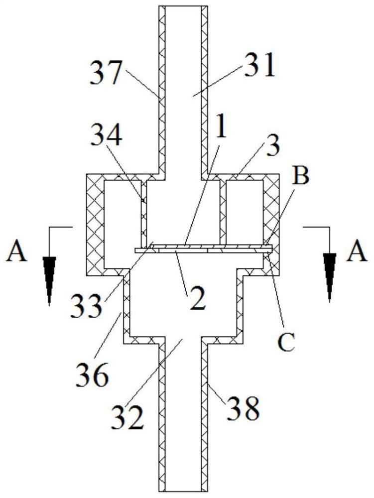
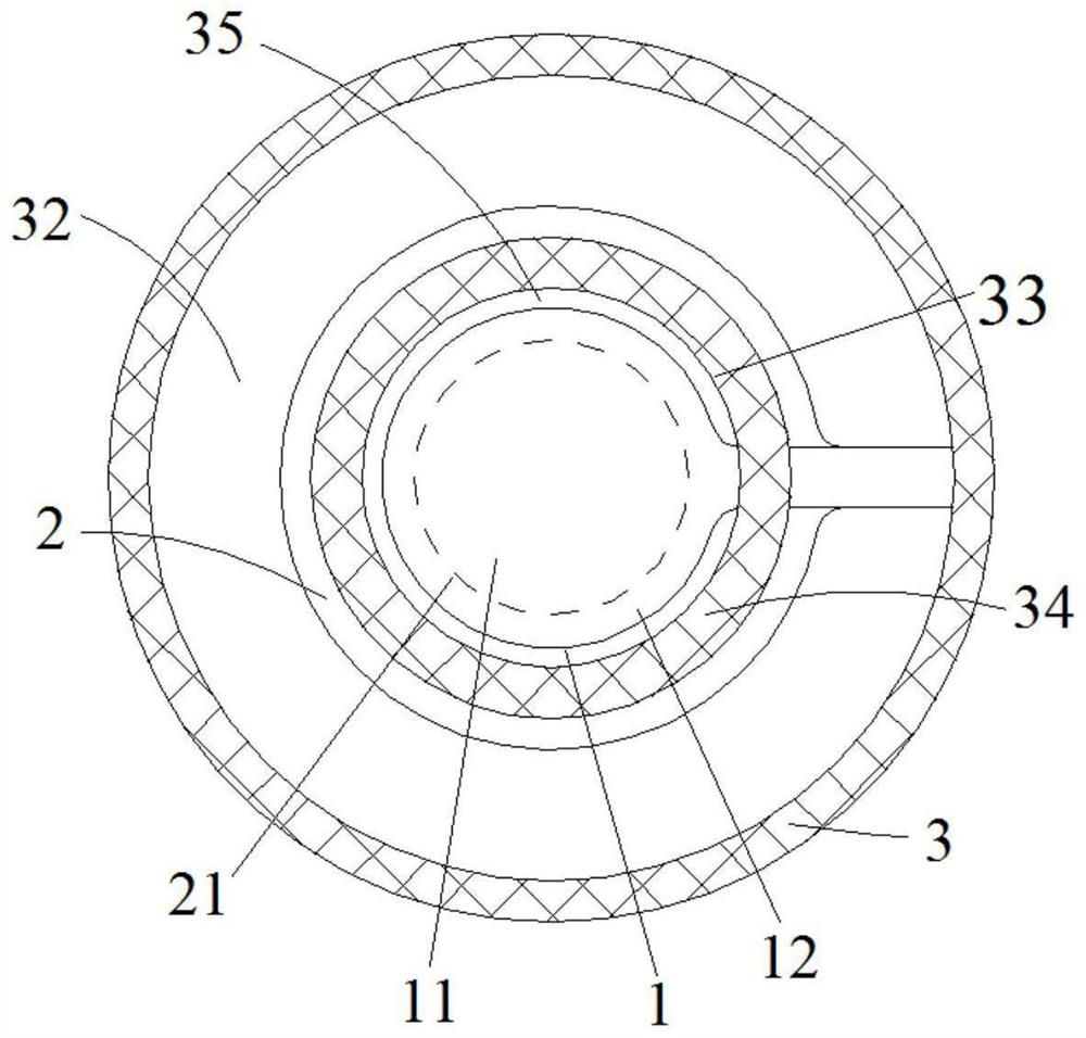
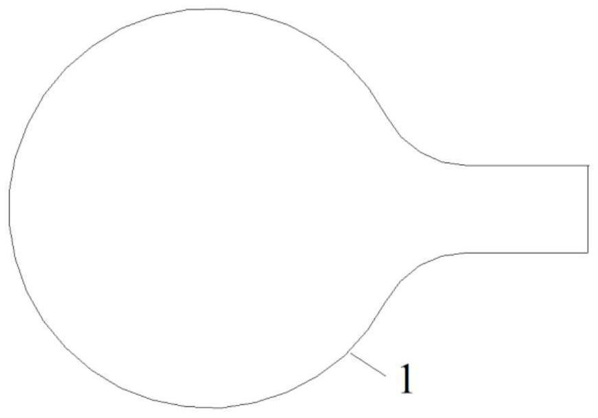
[0048] Embodiment 1 of the valve provided by the present invention is applied to the fuel tank ventilation pipeline of the engine-driven generator. The valve specifically includes a valve body 3 , and a first chamber 31 and a second chamber 32 are disposed through the valve body 3 . Inside the valve body 3, the first chamber 31 is docked with the second chamber 32, and the first valve plate 1 with elasticity and the second valve plate 2 with elasticity are arranged at the interface 33, specifically, the first valve plate 1 and the second valve plate 2 are reeds. Wherein, the first chamber 31 and the second valve plate 2 are respectively located on two sides of the first valve plate 1 .

[0049] Since the first valve piece 1 and the second valve piece 2 have elasticity, during the working process, according to the pressure difference on both sides of the docking port 33, the first valve piece 1 and the second valve piece 2 are adaptively deformed, thereby changing the first va...


PUM


Abstract

The invention discloses a valve and an engine-driven generator using the same. The valve comprises a valve body, and a first cavity and a second cavity are formed in the valve body in a penetrating mode. The first cavity and the second cavity are in butt joint, a first elastic valve plate and a second elastic valve plate are arranged at the butt joint opening, and the first cavity and the second valve plate are located on the two sides of the first valve plate respectively. The second valve plate is provided with a valve plate through hole, when the first valve plate and the second valve plate are both in a reset state, the first valve plate covers the valve plate through hole in a sealing mode, and the second valve plate and the first valve plate are matched to seal the butt joint opening. The first valve plate can swing into the first cavity or the second cavity from the butt joint opening through deformation, and when the first valve plate swings into the first cavity, the first cavity communicates with the second cavity through the valve plate through hole. The second valve plate can swing to the second cavity from the butt joint opening through deformation. According to the valve, one-way oil passing prevention and two-way ventilation of the first cavity and the second cavity can be achieved. The on-off condition of the valve can be controlled only by arranging the two elastic valve plates, so that the structure of the valve is simplified.

Description

technical field [0001] The invention relates to the technical field of power equipment, in particular to a valve and an engine-driven generator. Background technique [0002] Portable, silent engine-driven generators (sometimes directly referred to as generators) have small power (for example, the output power is 3 to 15KW), and their engine / generator units are built into a roughly square box-shaped case to The operating noise is minimized, and a handle is provided on the chassis for easy handling. [0003] For this kind of generator, in order to meet the fuel evaporation emission requirements in the fuel tank and the fuel tank ventilation requirements, a carbon canister can be installed in the chassis. communicated with the atmosphere. In this way, during normal operation, the internal pressure in the fuel tank decreases due to fuel consumption, and the pressure in the tank needs to be kept in communication with the atmosphere through the carbon tank pipeline to ensure th...

Claims


Application Information

Patent Timeline
IPC IPC(8): F16K17/24
CPCF16K17/24
Inventor 柯卫赵飞
Owner 重庆隆鑫新能源科技有限公司
Learn More