
Microfluidic device and control equipment for microfluidic device

a microfluidic device and control equipment technology, applied in the direction of liquid degasification, separation process, laboratory glassware, etc., can solve the problems of inefficient design valves imposing major problems, and achieve the effect of simple valve structure, convenient use and easy manufacturing

Active Publication Date: 2020-09-10
UNIST ULSAN NAT INST OF SCI & TECH
View PDF0 Cites 0 Cited by
  • Summary
  • Abstract
  • Description
  • Claims
  • Application Information

AI Technical Summary

Benefits of technology

This patent aims to improve the operation of valves that control fluid flow by making them more effective. This is achieved through a simple valve structure that is easy to manufacture and use.

Problems solved by technology

An inefficiently designed valve can impose a major problem, such as the development of point-of-care diagnosis devices that require automation of the entire process from sample injection to outcome detection.

Method used


Image

  • Microfluidic device and control equipment for microfluidic device
  • Microfluidic device and control equipment for microfluidic device
  • Microfluidic device and control equipment for microfluidic device

Examples


Embodiment Construction

[0041]Hereinafter, with reference to the attached drawings, embodiments of the present invention will be described so that a person ordinarily skilled in the art can readily conduct.

[0042]As can be readily appreciated by the person ordinarily skilled in the art, embodiments described below can be modified in various forms to the extent not departing from the spirit and scope of the invention.

[0043]Wherever possible, the same or similar parts are denoted using the same reference numerals in the drawings.

[0044]The terminology used below are merely to refer to a particular embodiment and are not intended to limit the present invention.

[0045]As used herein, the singular forms also include the plural forms unless the context clearly indicates otherwise.

[0046]The meaning of “comprising” or “including” as used in the specification embodies specific characteristics, regions, integers, steps, operations, elements, and / or components, and it does not exclude the presence or addition of other c...


PUM

PropertyMeasurementUnit
diameteraaaaaaaaaa
internal diameteraaaaaaaaaa
elasticityaaaaaaaaaa

Abstract

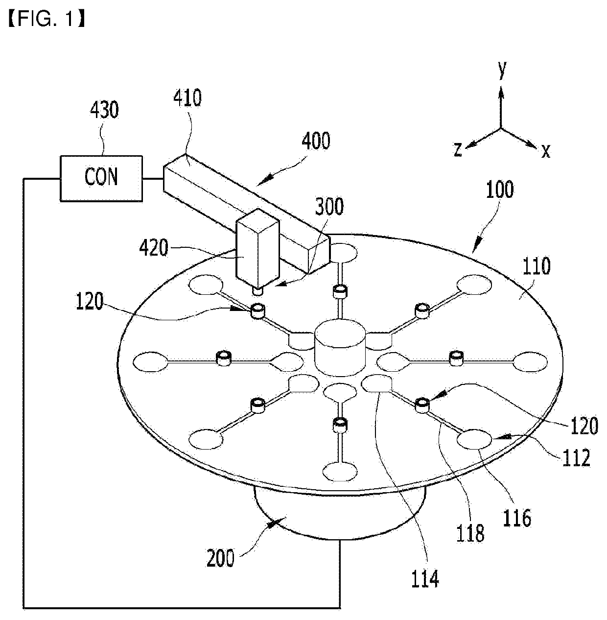
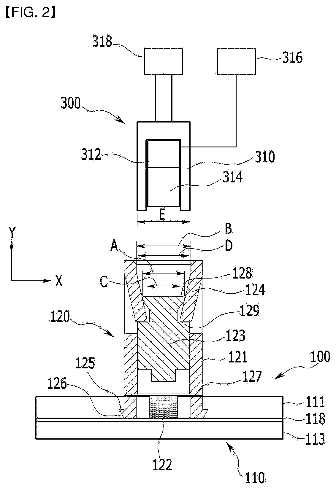
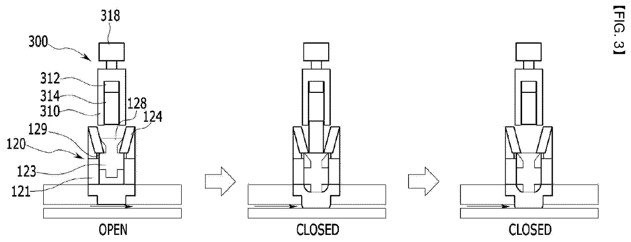
Provided is a microfluidic device to more easily and effectively operate a valve by improving the structure of valves for controlling a fluid flow more simply and efficiently, which comprises a platform having at least one chamber, at least one flow channel connected to the chambers and transfer fluid, and a valve which opens or closes the flow channel, wherein the valve comprises a body installed in the platform, a blocking plate installed in the body and positioned to face the flow channel to selectively blocks the flow channel, a pressing rod installed to be movable at the inside of the body to press the blocking plate, and a fixing unit installed at the body and fix the pressing rod at a blocking plate pressing position.

Description

CROSS-REFERENCE TO RELATED APPLICATION[0001]This application claims priority to and the benefit of Korean Patent Application No. 10-2017-0141393 filed in the Korean Intellectual Property Office on Oct. 27, 2017, the entire contents of which are incorporated herein by reference.BACKGROUND OF THE INVENTION(a) Field of the Invention[0002]The present invention relates to a microfluidic device and a control equipment for the microfluidic device to control a fluid flow.(b) Description of the Related Art[0003]A microfluidic device performs a unit operation by controlled flow of liquids in a small scale. Valves help combine those unit operations to integrate more complex functions in a single device by controlling chambers which contain fluids.[0004]The valve is one of the most important elements for fluid control in research which uses a microfluidic.[0005]The fluid flow can be controlled by operating valves.[0006]Through this, it is possible to integrate a number of functions on a single ...

Claims


Application Information

Patent Timeline
Patent Type & Authority Applications(United States)
IPC IPC(8): B01L3/00
CPCB01L2300/123B01L2400/06B01L2300/041B01L3/502715B01L2300/0806B01L2300/06B01L3/502738B01D19/00B01L3/00B01L2400/0655F16K99/0015F16K99/0046F16K2099/0069F16K2099/0071F16K2099/0084
Inventor CHO, YOON KYOUNGLEE, KYUSAOGLEE, YONGJIN
Owner UNIST ULSAN NAT INST OF SCI & TECH
Learn More