
Modularized multifunctional variable valve actuation system for use in 6-cylinder internal combustion engine

a multi-functional, variable technology, applied in the direction of valve arrangements, machines/engines, non-mechanical valves, etc., can solve the problems of increasing the loss of properties and people's lives due to traffic accidents, consuming a large amount of gasoline, and affecting the sustainable development of the economy, so as to improve the acceptance of the market, simplify the electromagnetic valve structure, and reduce the effect of system cos

Inactive Publication Date: 2018-08-28
DALIAN UNIV OF TECH
View PDF5 Cites 0 Cited by
  • Summary
  • Abstract
  • Description
  • Claims
  • Application Information

AI Technical Summary

Benefits of technology

[0017]The purposes of the present disclosure include: 1) by means of introducing phase limit modules, a few of oil supply modules and electromagnetic valves, as well as simple electromagnetic valves, are combined to achieve the function of a variable valve required in the drive and brake mode of an internal combustion engine, so as to combine the variable valve technology and auxiliary braking technology of the internal combustion engine, simplify the system to a large extent, and lower the cost; 2) simplifying structures of key components of the system, e.g. phase limit module, reducing the quantity of external oil pipes, optimizing the manufacturability of components and lowering the cost; 3) adopting the modularized design method to make functions of all parts of the system independent, so as to select components of the system according to the practical requirements, instead of changing components and the layout of the system, thus intensifying the adaptability of the system to engine types, extending the application scope of the system, and improving the acceptance of the system in the market.
[0028]Benefits of the present disclosure are: (a) the modularized multifunctional variable valve actuation system for a six-cylinder internal combustion engine needs only two oil supply modules to supply hydraulic oil for all intake (exhaust) valve actuation modules of the engine, it needs only two oil supply modules and two two-position two-way valves to realize the continuously variable valve event, and it needs only two oil supply module, two two-position three-way valves and one two-position two-way valve to realize the fully variable valve event. Its oil supply modules and electromagnetic valves are reduced to a large extent, the simplification of its electromagnetic valve structure largely reduces the system cost and improves the acceptance of the market; (b) the impact of the oil supply module operation phase on the valve operation process is weakened. In particular, the valve closing process is not restricted by the operation phase of the oil supply module, and the idling, low-speed and medium-speed performance of the internal combustion engine can be optimized further by closing the intake valve earlier, so as to improve the oil consumption and exhaust of vehicles in the operation process and expand the system application effect; (c) the phase limit module structure is simplified a lot, less oil pipes are assembled externally, and the system manufacturability and practicability is enhanced. Meanwhile, independent with the phase limit module and the mode selection module, it is more compatible with internal combustion engines without a brake mode or with different brake modes; (d) by means of modularized design, functions of various components of the system are independent, parts can be selected according to actual application requirements, and other parts of the system are not affected. The system has high adaptability for engine types and is applicable widely: the setup of the mode selection module can be decided depending on the brake mode; the mode selection module structure can be selected according to the brake mode and the drive pattern of the mode selection module; control modules and oil delivery modules can be selected according to the variability and flexibility of valves, the speed range of internal combustion engines and their special layout and so on. The opening angle of each oil port section of a phase limit module spindle can be adjusted according to the ignition sequence of an internal combustion engine. For the internal combustion engine with a brake mode, the connection object of oil path between the phase limit module and the mode selection module can be changed; for the internal combustion engine without a brake mode, the connection object of oil path between the phase limit module and the valve actuation module of each cylinder can be changed; (e) the mode selection module will combine the variable valve technology and auxiliary braking technology of internal combustion engines together, so as to use less auto accessories, largely reduce the cost and enhance functions of the system; (f) various components of the system are connected via an oil pipes, which is beneficial for its layout on application vehicles.

Problems solved by technology

With the rapid development of world economy, energy and environmental problems have adversely affected the sustainable development of economy.
Internal combustion engines are widely used, consume a large amount of gasoline and produce many harmful exhaust gases and particles.
In addition, with the rapid increase of the number of internal combustion engines worldwide, losses in properties and people's lives due to traffic accidents grow year by year.
However, at present, most auxiliary braking systems, e.g. eddy current retardant module and hydraulic retardant module, exhibit problems during operation.
For instance, brake parts overheat easily, the brake efficiency diminishes quickly, the controllability of braking ability is low, the vehicle tends to deviate while braking, and the brake system occupies too much space.
Among current auxiliary braking systems of engines, the brake efficiency of a 720° C.A / cycle compression release engine brake system is the highest, but this system also has problems with brake power.
Meanwhile, the structure of the cam-less systems is complicated, the cost is high and the reliability, durability and thermal expansion compensation control, etc. leave much to be desired.
Electro-hydraulic systems leave much to be desired in terms of movement accuracy control and valve lift adjustability.
Common rail oil supply systems are not equipped with distribution cams and adjust the opening / closing timing and maximum valve lift by controlling the open / close state of the electromagnetic valve and the actuation oil in the energy storage.
With the increase of the cylinder number, single cylinder valve numbers and speeds of internal combustion engines, common rail oil supply systems still have the following defects: 1) the volume of common rail tube is high and the space layout is difficult; 2) too many electromagnetic valves with high speed and large flow rate are applied in the system, and materials and technical processes of electromagnetic valves decide their high cost.
Therefore, the overall cost of the common rail oil supply systems is high.
Therefore, also, it is more difficult to utilize traditional common rail oil supply electro-hydraulic variable valve actuators.
However, improvement is still required with regard to the following two aspects: first, the system needs more oil feeders and electromagnetic valves and its overall cost is high; second, the adjustable operating range of a valve affects the limit of oil supply and control devices, so it can neither realize the independent adjustment among the opening / closing timing and valve lift nor the 360° C.A / cycle valve operation process required by the auxiliary braking mode of an internal combustion engine.
However, such a system still has the following problems: 1) the system has too many electromagnetic valves and its cost is high; 2) the adjustable range of its valve actuator is restricted to the oil supply rate of its cam-plunger oil feeder; it is impossible to open the exhaust valve secondarily and change the 720° C.A / cycle mode of an internal combustion engine to the 360° C.A / cycle compressor brake mode, which restricts the extension of its functions.
However, the dual-mode fully variable valve actuation system still has several defects: 1) as the two-position five-way valve of this system needs to the switched under the different pressure differences of each oil port and the pressure difference change of each oil port is extremely complicated, with the speed increase, the response time of the two-position five-way valve shall be shorter to ensure higher flow rate.
Therefore, the two-position five-way valve has complicated structure and the processing cost thereof is high; 2) under the drive mode of the internal combustion engine, this system cannot close the valve when the oil feeder is working, which restricts the performance improvement of this system at idle or at the medium and low speed.
While idling or the medium and low speed are common running conditions for urban vehicles, and the operation of the internal combustion engine under these running conditions basically decides the actual oil consumption and emission of the vehicles; 3) the structure of the drive-brake circulator is complicated, more external oil pipes are required, the system manufacturability is low, the production cost is high and its structural layout is difficult; 4) functions of various components of the system are mutually reliable, and the overall layout of the system and many components need to be changed according to different application requirements, which restricts the application range of the system.
However, this system still has the following two defects: 1) the cycle selector structure is complicated, more oil pipes are required, the system manufacturability is lower, its cost is higher and its layout is more different; 2) functions of various components of the system are mutually dependent, and the overall layout of the system and many components need to be changed according to different application requirements, which restricts the application scope of the system.

Method used


Image

  • Modularized multifunctional variable valve actuation system for use in 6-cylinder internal combustion engine
  • Modularized multifunctional variable valve actuation system for use in 6-cylinder internal combustion engine
  • Modularized multifunctional variable valve actuation system for use in 6-cylinder internal combustion engine

Examples


Embodiment Construction

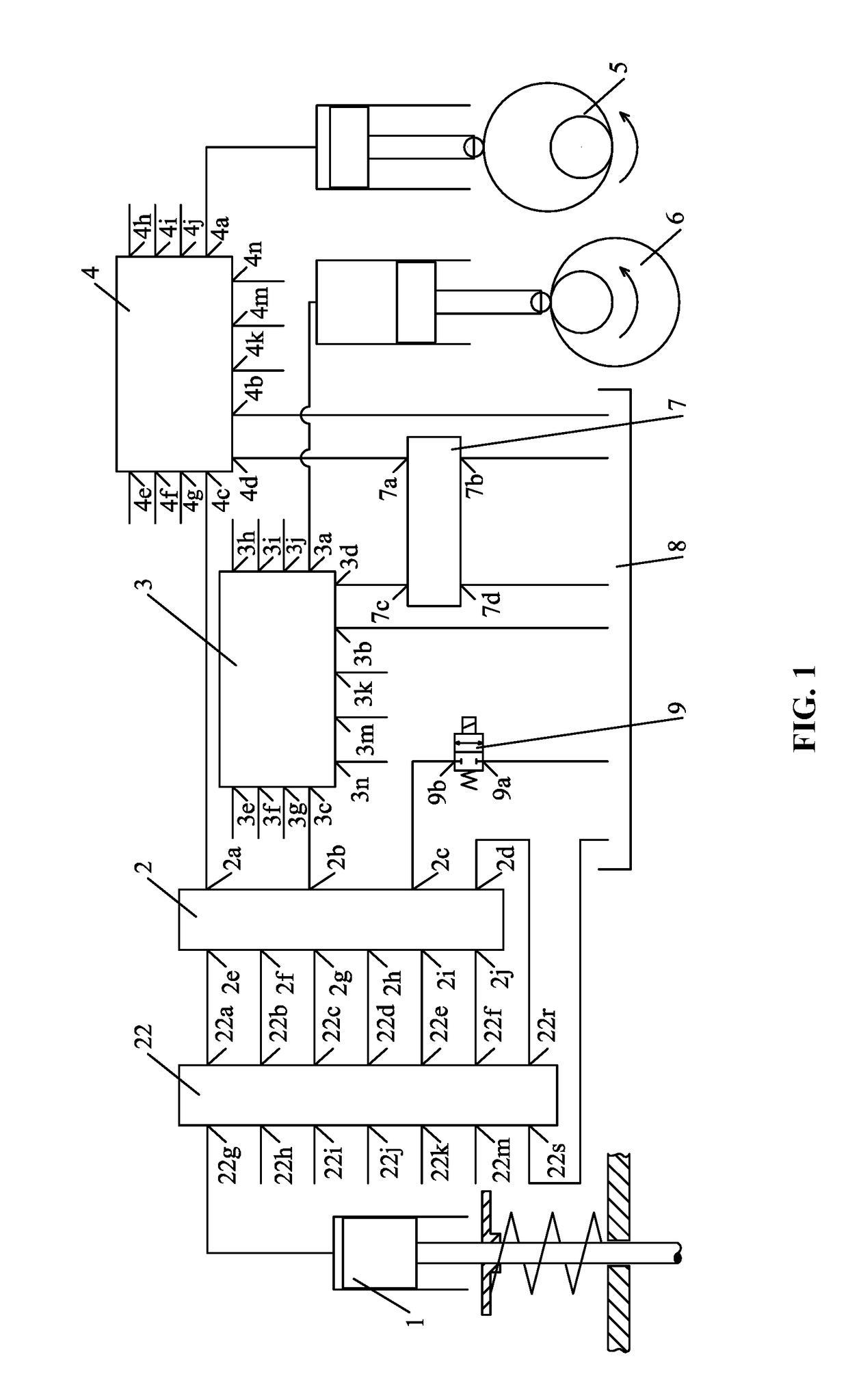
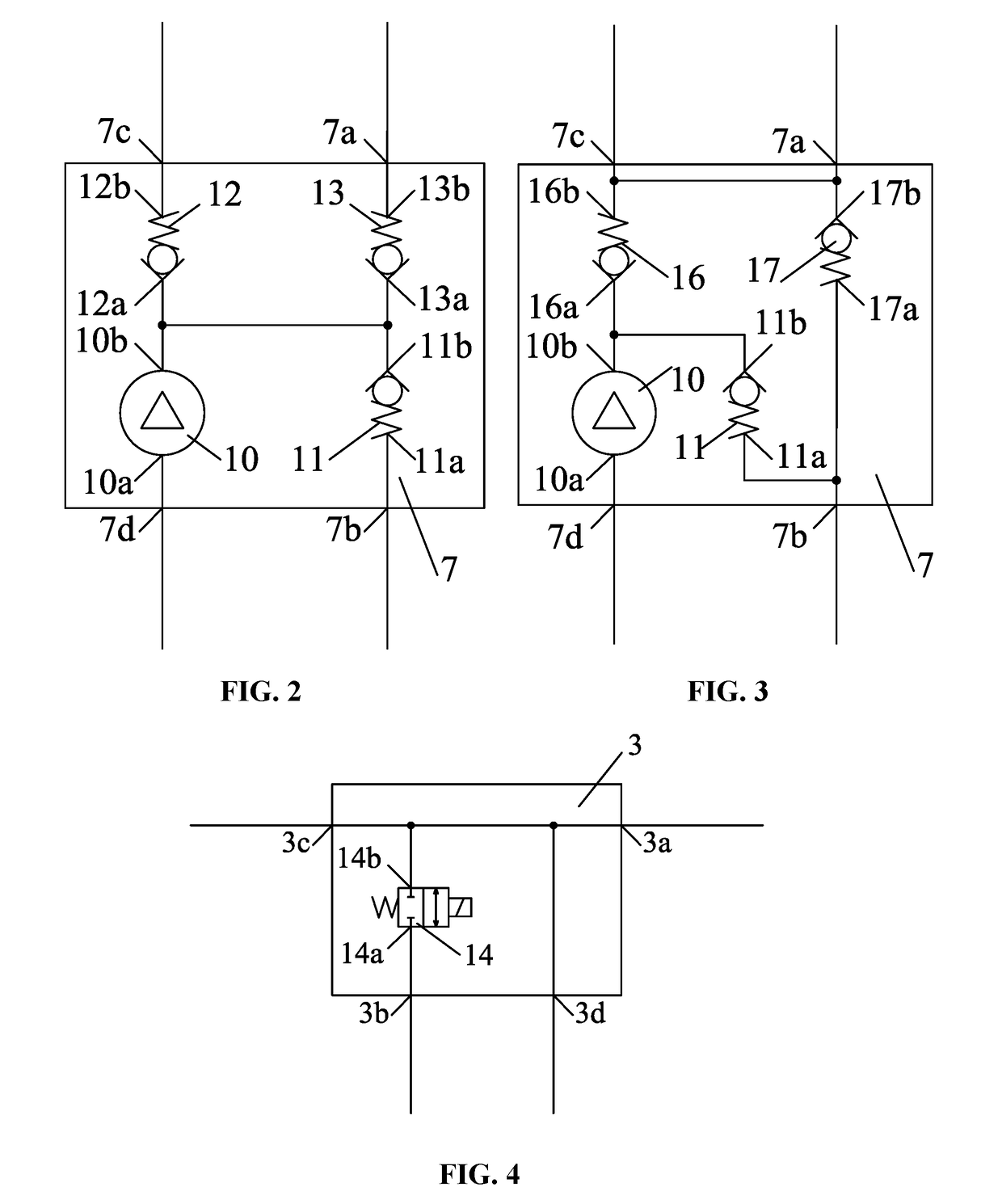
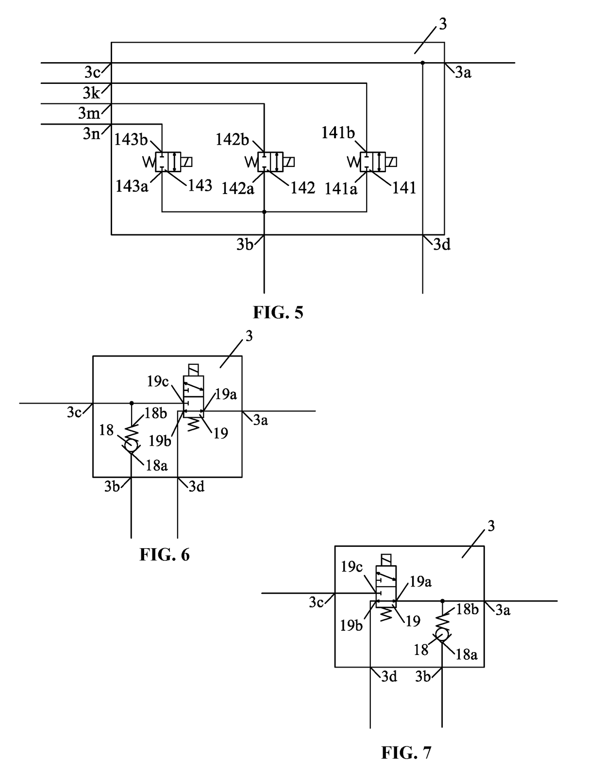
[0105]FIG. 1 shows a diagram of a modularized multifunctional variable valve actuation system for a six-cylinder internal combustion engine. This system mainly comprises the valve actuation module 1, the first oil supply module 6, the second oil supply module 5, oil delivery module 7, oil tank 8, oil drain valve 9 and oil pipe; besides, it also comprises the phase limit module 2, mode selection module 22, the first control module 3, the second control module 4; The first oil supply module 6 and the second oil supply module 5 are cam-plunger oil supply modules with the camshaft angle with the phase difference of 180° and its rotation period is double of the ignition interval angle of the internal combustion engine, i.e. 240° crank angle. The first control module 3 comprises the first oil supply port 3a, the oil drain port 3b, the 1 drive port 3c and the oil delivery port 3d of the first control module. The second control module 4 comprises the first oil supply port 4a, the oil drain ...


PUM


Abstract

A modularized multifunctional variable valve actuation system for use in a six-cylinder internal combustion engine. The system includes two fuel supply modules that cooperate with two two-way two-position valves for implementing a continuously variable valve event, and that cooperate with two three-way two-position valves and one two-way two-position valve for implementing a fully variable valve event.

Description

CROSS-REFERENCE TO RELATED APPLICATIONS[0001]This application is a National Stage Appl. filed under 35 USC 371 of International Patent Application No. PCT / CN2014 / 000225 with an international filing date of Mar. 10, 2014, designating the United States, now pending, and further claims priority benefits to Chinese Patent Application No. 201310738155.0 filed Dec. 28, 2013. The contents of all of the aforementioned applications, including any intervening amendments thereto, are incorporated herein by reference. Inquiries from the public to applicants or assignees concerning this document or the related applications should be directed to: Matthias Scholl P.C., Attn.: Dr. Matthias Scholl Esq., 245 First Street, 18th Floor, Cambridge, Mass. 02142.FIELD OF THE INVENTION[0002]The present disclosure relates to a variable valve actuation system of internal combustion engines, and more particularly to a modularized multifunctional variable valve actuation system of six-cylinder internal combusti...

Claims


Application Information

Patent Timeline
Patent Type & Authority Patents(United States)
IPC IPC(8): F01L1/047F01L1/344F02B75/18F01L13/06F01L9/02F01L9/10F01L9/14F01L9/40
CPCF01L13/06F01L1/047F01L1/3442F01L9/025F01L13/065F02B75/18F02B2075/1824F01L2001/34426F01L2820/03F01L2820/033F01L2820/034F01L9/14
Inventor CUI, JINGCHENLONG, WUQIANGTIAN, JIANGPINGTIAN, HUAYANG, TIANHAOWANG, DANTING
Owner DALIAN UNIV OF TECH
Learn More