Autofocus motion compensation method of airborne ultra-high resolution SAR (Synthetic Aperture Radar) back projection image

An ultra-high resolution and motion compensation technology, applied in the field of radar, can solve the problems of not considering the phase error of high-frequency motion, abnormal complexity, and large amount of calculation, and achieve the effect of expanding the focus range of the scene and improving the focus of the focus point and target

Active Publication Date: 2015-01-28
NANJING UNIV OF POSTS & TELECOMM
View PDF4 Cites 26 Cited by
  • Summary
  • Abstract
  • Description
  • Claims
  • Application Information

AI Technical Summary

Problems solved by technology

However, the existing autofocus methods do not take into account the high-frequency motion phase error; the BP image autofocus processing based on the principle of maximizing image clarity is computationally intensive and extremely complex; in addition, the geometric space-based decomposition autofocus processing need to rely on high-precision motion measurement system
In the existing methods, considering the use of polar coordinate format grids for projection imaging, it can o

Method used


Image

  • Autofocus motion compensation method of airborne ultra-high resolution SAR (Synthetic Aperture Radar) back projection image
  • Autofocus motion compensation method of airborne ultra-high resolution SAR (Synthetic Aperture Radar) back projection image
  • Autofocus motion compensation method of airborne ultra-high resolution SAR (Synthetic Aperture Radar) back projection image

Examples


Embodiment Construction

[0044] Below in conjunction with accompanying drawing, technical scheme of the present invention is described in further detail:

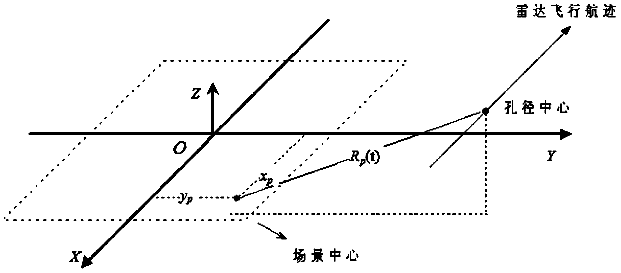
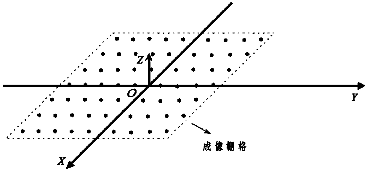
[0045] Figure 1a is the spatial geometric relationship diagram of spotlight SAR data acquisition, where the center of the scene is the origin of the coordinate system, and the radar platform moves along the X axis at a speed v t Flying at a constant altitude h, the backprojection grid is set along the ground plane, R P (t) means that the coordinates are (x p ,y p ) The instantaneous distance from the point target to the radar track, x p and y p are the coordinates of the target along the X-axis and Y-axis respectively (in view of the radar platform flying along the X-axis, x pAlso known as azimuth coordinates). Figure 1b is the back projection imaging model diagram.

[0046] The frequency modulation slope of the radar transmission is k, and the carrier frequency is f c The chirp signal, based on the wave equation and the Born approximation...


PUM


Abstract

The invention discloses an autofocus motion compensation method of an airborne ultra-high resolution SAR (Synthetic Aperture Radar) back projection image. The phase error introduced by the deviation of a flight path cannot be fully compensated through a radar platform motion sensor under the condition of high resolution and accordingly the image focusing quality is affected. The target defocusing can exist along different inclined directions in the image reconstruction by a back projection algorithm, the target distance migration cannot be strictly limited within a distance resolution cell, and the traditional autofocus processing fails. The correction is performed on the sub-bandwidth autofocus motion compensation processing of an imaging grid; the data collection is performed on the inclined plane after the correction for image reconstruction and the space-variant characteristics of the target defocus direction is completely removed; the sub-bandwidth decomposition is performed on back projection processing data and the phase gradient autofocus and splicing is performed to obtain a refocused image. Compared with the existing algorithm, the high-order motion phase error is considered and the effective compensation of the phase error in the image reconstruction by the back projection algorithm is implemented.

Description

technical field [0001] The invention relates to the field of radar technology, in particular to a self-focusing motion compensation method for an airborne ultra-high resolution SAR back-projection image. Background technique [0002] Back projection (BP) algorithm is a classic time-domain imaging method of Synthetic Aperture Radar (SAR). In BP processing, the SAR echo data is obtained through space-variant back-projection and azimuth matched filtering, and the calculation load is very large. In practical applications, the fast back-projection method is usually used instead of BP to achieve efficient focused imaging of SAR data. In the present invention, BP and various fast back-projection methods are collectively referred to as back-projection algorithms. The back-projection algorithm has high precision and can achieve good focus of SAR data under any known track conditions. It has been widely used in large squint, nonlinear aperture, dual (multi-base) and new system SAR c...

Claims


Application Information

Patent Timeline
IPC IPC(8): G01S13/90
CPCG01S13/90G01S13/9017G01S13/9019
Inventor 王昕朱剑蒋锐
Owner NANJING UNIV OF POSTS & TELECOMM
Why Eureka
Try Eureka