Movement compensation method of surgical robot for positioning and guiding for bone surgery

A technology of robot movement and surgical robot, which is applied in the field of computer-aided minimally invasive therapy, can solve problems such as unavailability of analytical algorithms, prolonged operation time, radiation and image processing time, etc.

Inactive Publication Date: 2015-07-29
TSINGHUA UNIV
View PDF0 Cites 34 Cited by
  • Summary
  • Abstract
  • Description
  • Claims
  • Application Information

AI Technical Summary

Problems solved by technology

However, the doctor needs to manually move the surgical tool multiple times to make its projection in the images of various viewing angles meet the implantation requirements, which prolongs the operation time
Compared with 2D fluoroscopic navigation, 3D fluoroscopic navigation can provide more spatial information, making path planning easier, but 3D fluoroscopic navigation usually requires intraoperative 3D data acquisition, which prolongs the time for radiation and image processing
Since the improved target mask moves with the image intensifier of the C-arm X-ray machine, the external perspective parameters of the C-arm X-ray machine imaging cannot be obtained using analytical algorithms, so the traditional method cannot be used for C-arm X-ray imaging. Machine Calibration and Rebuild

Method used


Image

  • Movement compensation method of surgical robot for positioning and guiding for bone surgery
  • Movement compensation method of surgical robot for positioning and guiding for bone surgery
  • Movement compensation method of surgical robot for positioning and guiding for bone surgery

Examples


Embodiment Construction

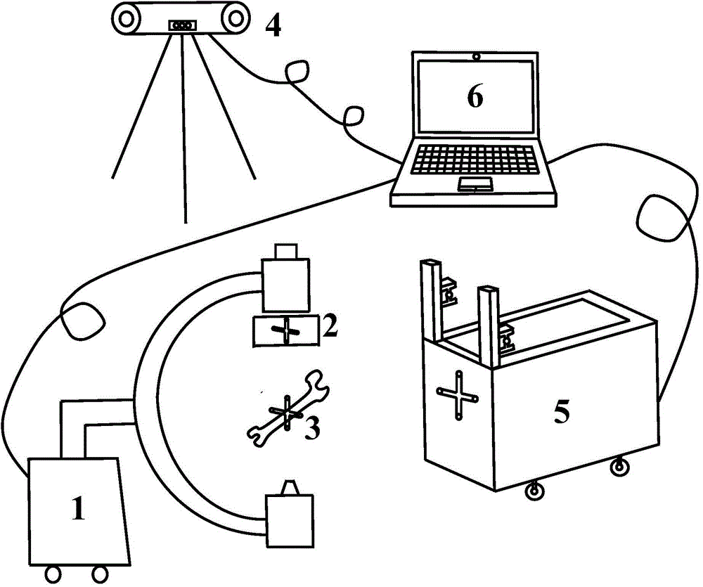
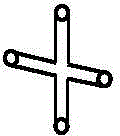
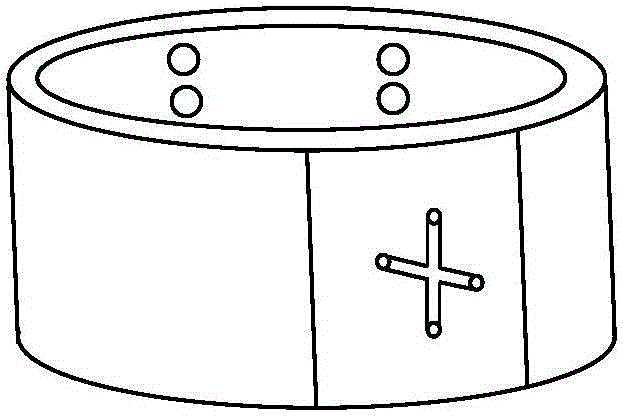
[0116] Based on the above ideas, we propose a method of using the optical positioning subsystem to establish the dynamic connection between the intraoperative image, the target mask, the patient and the biplane surgical robot to realize the motion compensation of the biplane surgical robot, and design a corresponding Operating procedures. The target mask fixed on the image intensifier of the C-arm X-ray machine is used to replace the stereo calibration frame of the traditional double-plane surgical robot body, which reduces the difficulty of obtaining images; the optical positioning subsystem is used to obtain the outer surface of the C-arm X-ray machine. The perspective parameters are used to calibrate and reconstruct the C-arm X-ray machine, so as to establish a dynamic connection between the optical positioning subsystem, image, target mask, patient and biplane surgical robot, and achieve the effect of motion compensation. The method has reliable precision and can reduce op...


PUM


Abstract

The invention provides a movement compensation method of a surgical robot for positioning and guiding for bone surgery, and belongs to the technical field of CAD minimally invasive bone surgery treatment. The method is characterized in that a target cover fixed on an image intensifier of a C-shaped arm X-ray machine replaces the traditional three-dimensional calibration frame, so that the operation time and radiation quantity can be reduced; meanwhile, a tracer fixed on the target cover is used for acquiring the image exterior perspective parameters of the C-shaped arm X-ray machine through an optical positioning subsystem; the DLT method is adopted to solve the interior perspective parameters; the route is planned and reconstructed according to the pole line geometric principle and binocular vision algorithm; the tracers are also fixed on a patient and a double-plane surgical robot and used for tracking the location; therefore, a spatial coordinate transmission relationship among the image, the target cover, the patient and the double-plane surgical operator is built; the spatial transformation matrix is utilized to solve the problem of dynamic coordinate error caused by opposite movement of the double-plane surgical robot and the patient while reducing the surgical operation time and the radiation quantity on the basis of automatic accurate positioning of the traditional double-plane surgical robot.

Description

Technical field: [0001] The invention belongs to the field of computer-aided minimally invasive treatment, and is especially suitable for the guidance of minimally invasive fixation operations for orthopedic trauma such as femoral neck fractures and sacroiliac joint fractures. Background technique: [0002] Femoral neck and sacroiliac joint fractures are common orthopedic traumas, and internal fixation with cannulated compression screws is increasingly used in minimally invasive clinical treatment of femoral neck and sacroiliac joint fractures. For femoral neck fractures, it is required that the three hollow compression screws implanted should be parallel to each other, have a reasonable spatial distribution, and their tips should be fixed on the cortical bone layer and cannot pass through the bone cortical layer; for sacroiliac joint fractures, it is necessary to ensure that the implanted The inserted cannulated compression screw avoids the main arteries and nerves in the p...

Claims


Application Information

Patent Timeline
Patent Type & Authority Applications(China)
IPC IPC(8): A61B17/90
CPCA61B17/88A61B2017/00238A61B17/90
Inventor 王广志宋健丁辉王军强韩巍
Owner TSINGHUA UNIV
Why Eureka
Try Eureka