Angiography machine enabling laser positioning to be convenient

A technology of laser positioning and radiography machine, which is applied in the field of surgical medical equipment, can solve problems such as low precision and troublesome operation, and achieve the effects of flexible operation, convenient adjustment, and accurate positioning and guidance

Inactive Publication Date: 2014-01-08
THE FIRST AFFILIATED HOSPITAL OF SUN YAT SEN UNIV
View PDF4 Cites 8 Cited by
  • Summary
  • Abstract
  • Description
  • Claims
  • Application Information

AI Technical Summary

Problems solved by technology

However, when the angiography machine is used for CT-guided puncture, one of the cross-shaped lasers must be adjusted to be parallel to the C-arm plane, and then the cross point is positioned to the puncture point, which is troublesome.
Moreover, the four joints of the bracket 100 are relatively free to move, and professional training is required to skillfully adjust one of the crosshair lasers to be parallel to the plane of the C-arm. At the same time, the subjective judgment of the operator is involved, and the accuracy is not high.

Method used


Image

  • Angiography machine enabling laser positioning to be convenient
  • Angiography machine enabling laser positioning to be convenient
  • Angiography machine enabling laser positioning to be convenient

Examples


Embodiment 1

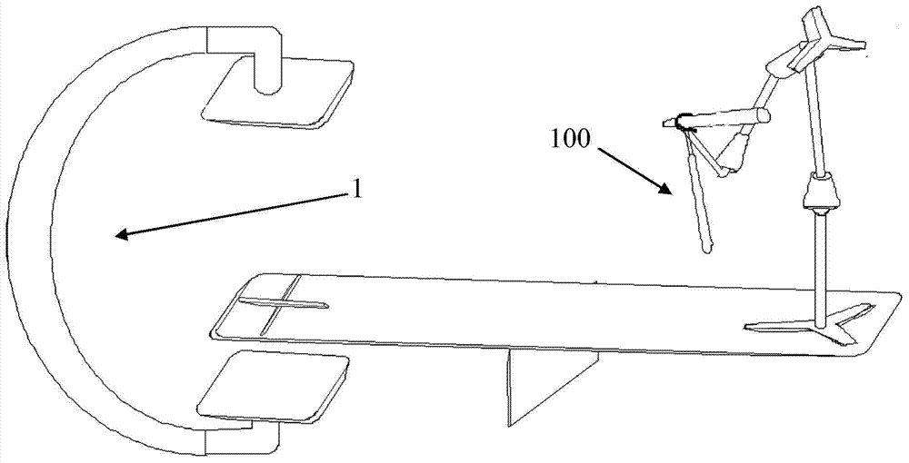
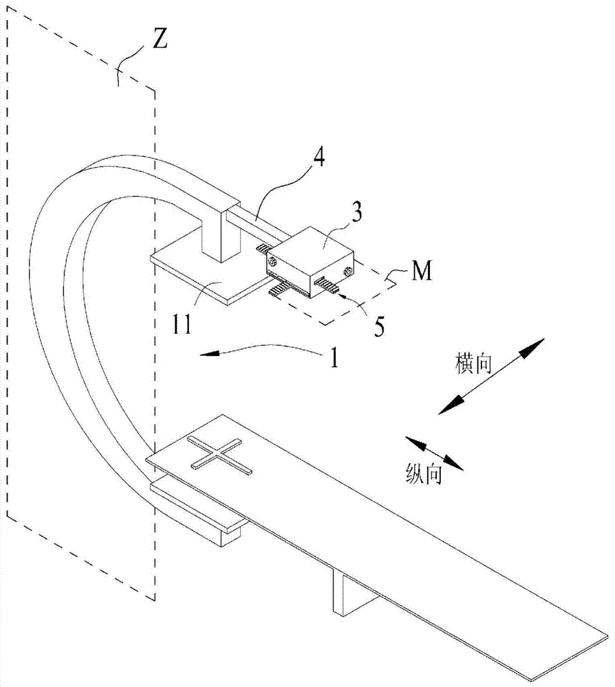
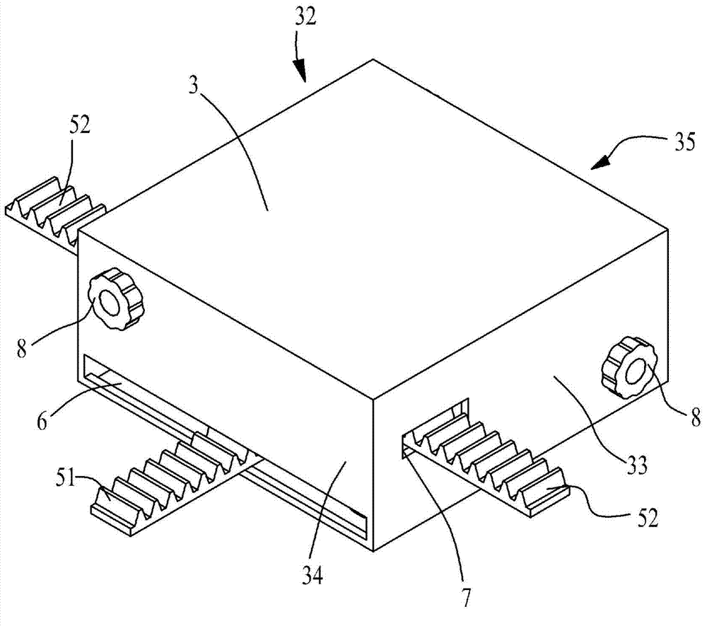
[0025] Such as figure 2 , Figure 5 An angiography machine for laser positioning is shown, which includes a C-arm 1, a cross laser 2 for emitting a cross-shaped laser, and a support box 3 with a bottom opening 31. The C-arm 1 of this embodiment adopts Philips FD20 Angiography machine C-arm. The support box 3 is in the shape of a cuboid, and the support box 3 is fixedly connected with the C-arm 1 through the cross bar 4. An adjustment device 5 that can move vertically and horizontally in the support box 3 is installed in the support box 3. The moving plane M of the adjustment device 5 Parallel to the C-arm plane Z; the cross laser 2 is vertically fixed on the adjustment device 5, and protrudes downward from the bottom opening 31 of the support box 3, and the laser output direction of the cross laser 2 is parallel to the C-arm plane Z, The vertical and horizontal movement of the adjustment device 5 drives the cross laser to adjust its position on the plane Z parallel to the C...

Embodiment 2

[0031] Such as Figure 6 Shown is Embodiment 2 of the angiography machine of the present invention. The difference between this Embodiment 2 and Embodiment 1 is that the cross laser 2 is rotatably installed on the bottom surface of the first rack 51 and is connected by a hinge. The cross laser 2 is equivalent to It is hinged with the bottom surface of the first rack 51, and at the same time, the rotation plane of the cross laser 2 is parallel to the C-arm plane Z, that is, the cross laser 2 is limited to rotate in the rotation plane parallel to the C-arm plane Z, which is used for large-scale adjustment of the cross laser 2 The irradiation angle of the output laser.


PUM


Abstract

The invention discloses an angiography machine enabling laser positioning to be convenient. The angiography machine comprises a C-shaped arm and a cross laser used for emitting cross-line-shaped lasers, the C-shaped arm is arranged on a C-shaped arm plane, the angiography machine further comprises a supporting box with a bottom opening, the supporting box is fixedly connected with the C-shaped arm through a cross rod, an adjusting device capable of moving longitudinally and transversely in the supporting box is arranged in the supporting box, and the moving plane of the adjusting device is perpendicular to the C-shaped arm plane. The cross laser is arranged on the adjusting device, and stretches downwards out of the bottom opening of the supporting box, the laser output direction of the cross laser is parallel to the C-shaped arm plane, the longitudinal and transverse movement of the adjusting device drives the cross laser to move to be parallel to the C-shaped arm plane, and therefore the position of the cross-line-shaped lasers is adjusted. The angiography machine enables one of cross-line-shaped lasers emitted by the cross laser to be always parallel to the C-shaped arm plane of the angiography machine, and the position of the cross point of the cross-line-shaped lasers emitted by the cross laser can be adjusted conveniently and accurately.

Description

technical field [0001] The invention relates to surgical medical instruments, in particular to an angiography machine which facilitates laser positioning. Background technique [0002] Percutaneous interventional surgery (radiofrequency ablation, pathological biopsy, puncture drainage, etc.) plays an important role in clinical practice. XperGuide technology in Philips FD20 combines digital subtraction angiography (digital subtraction angiography, DSA) two-dimensional perspective real-time guidance with CT and MR imaging technology and applies it to percutaneous puncture interventional surgery, greatly improving interventional puncture surgery The accuracy of the operation reduces the trauma of the operation and the radiation dose of the doctor and the patient. At the same time, it can save the operation time, improve the treatment efficiency, and reduce the pain of the patient. Clinical practice has proved that this technology is safer, more effective and more economical th...

Claims


Application Information

Patent Timeline
Patent Type & Authority Applications(China)
IPC IPC(8): A61B6/08
Inventor 向贤宏黄坤杨建勇
Owner THE FIRST AFFILIATED HOSPITAL OF SUN YAT SEN UNIV
Why Eureka
Try Eureka