
Non-cross-feeding log-periodic antenna

A logarithmic periodic antenna, non-crossing technology, applied in logarithmic periodic antennas, non-resonant long antennas, etc., can solve the problems of large feeder line size, large antenna volume, and high profile, and achieve easy feeding and feeding. Simple way, easy miniaturization effect

Inactive Publication Date: 2015-01-28
HARBIN INST OF TECH
View PDF7 Cites 2 Cited by
  • Summary
  • Abstract
  • Description
  • Claims
  • Application Information

AI Technical Summary

Problems solved by technology

However, if the log-periodic antenna wants to obtain a wider frequency band, it is often at the cost of increasing the size, which makes the antenna bulky, heavy, and high-profile, which seriously limits the integrated application of the miniaturized system; at the same time, for the traditional log-periodic antenna due to The feed is often cross-fed from the shortest radiating oscillator end. Although this type of feed can improve the radiation efficiency in the high frequency band, it also makes the size of the feed line larger and limits the miniaturization of this type of antenna. applications in communication systems

Method used


Image

  • Non-cross-feeding log-periodic antenna
  • Non-cross-feeding log-periodic antenna
  • Non-cross-feeding log-periodic antenna

Examples


specific Embodiment approach 1

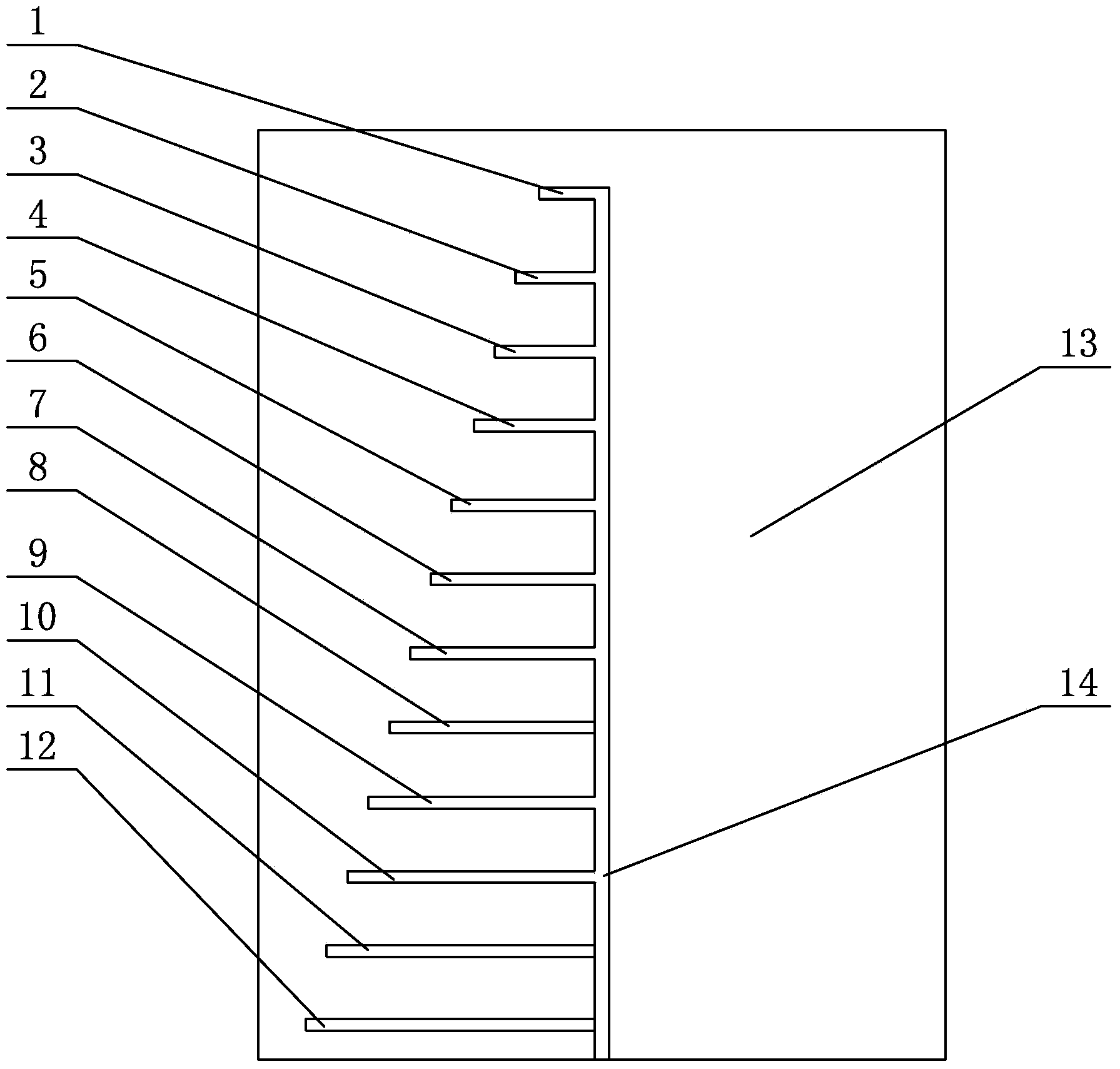
[0008] Specific implementation mode one: combine figure 1 To illustrate this embodiment, a non-cross-fed log-periodic antenna described in this embodiment includes a dielectric plate 13, two first horizontal metal strips 1, two second horizontal metal strips 2, two third Horizontal metal strip 3, two fourth horizontal metal strips 4, two fifth horizontal metal strips 5, two sixth horizontal metal strips 6, two seventh horizontal metal strips 7, two eighth Horizontal metal strips 8, two ninth horizontal metal strips 9, two tenth horizontal metal strips 10, two eleventh horizontal metal strips 11, two twelfth horizontal metal strips 12 and two Vertical metal strips 14, the medium plate 13 is a rectangular plate body, a vertical metal strip 14 is printed on the front and back sides of the medium plate 13 respectively, and the center line of each vertical metal strip 14 along the length direction is aligned with The medium plate 13 is parallel to the center line along the length ...

specific Embodiment approach 2

[0009] Specific implementation mode two: combination figure 1 Describe this embodiment, the length of the dielectric board 13 of a kind of non-cross-feed log periodic antenna described in this embodiment is 56mm, the width of the dielectric board 13 is 40mm, the thickness of the dielectric board 13 is 1mm, the dielectric board 3 The relative permittivity is 4.4. Other components and connections are the same as those in the first embodiment.

specific Embodiment approach 3

[0010] Specific implementation mode three: combination figure 1 Describe this embodiment, the length of the first horizontal metal strip 1 of the logarithmic periodic antenna of a kind of non-cross feed described in this embodiment is 0.89 times of the length of the second horizontal metal strip 2, the second horizontal metal strip The length of 2 is 0.89 times of the length of the third horizontal metal strip 3, the length of the third horizontal metal strip 3 is 0.89 times of the length of the fourth horizontal metal strip 4, and the length of the fourth horizontal metal strip 4 is the fifth 0.89 times of the length of the horizontal metal strip 5, the length of the fifth horizontal metal strip 5 is 0.89 times of the length of the sixth horizontal metal strip 6, and the length of the sixth horizontal metal strip 6 is the length of the seventh horizontal metal strip 7 0.89 times, the length of the seventh horizontal metal strip 7 is 0.89 times of the length of the eighth hori...


PUM


Abstract

The invention relates to an antenna, in particular to a non-cross-feeding log-periodic antenna. The contradiction of a traditional log-periodic antenna ultra wide band feature and antenna size is solved, and limitation on system integration application from a feeding mode is avoided. The non-cross-feeding log-periodic antenna comprises a dielectric plate, two first horizontal metal belt strips, two second horizontal metal belt strips, two third horizontal metal belt strips, two fourth horizontal metal belt strips, two fifth horizontal metal belt strips, two sixth horizontal metal belt strips, two seventh horizontal metal belt strips, two eighth horizontal metal belt strips, two ninth horizontal metal belt strips, two tenth horizontal metal belt strips, two eleventh horizontal metal belt strips, two twelfth horizontal metal belt strips and two vertical metal belt strips. The non-cross-feeding log-periodic antenna is used for the field of wireless communication.

Description

Technical field [0001] The invention relates to an antenna, in particular to a non-cross-feed log-periodic antenna, which belongs to the field of wireless communications. Background technique [0002] At present, ultra-wideband technology is an important development direction in the field of wireless communications, and has become one of the hot issues and research directions in the domestic and foreign communications circles in recent years. The development of communication technology has made communication systems have increasingly higher requirements for antenna indicators. In order to increase the communication rate, the antenna is required to have broadband characteristics. In addition, sometimes it is necessary to transmit time domain signals in the ultra-wideband spectrum range, and the antenna is also required to be stable. phase center, that is, the antenna is required to have miniaturization characteristics; in order to increase the communication distance, the ante...

Claims


Application Information

Patent Timeline
Patent Type & Authority Applications(China)
IPC IPC(8): H01Q11/10
Inventor 褚红军林澍成榕张雪莹张效衡
Owner HARBIN INST OF TECH
Learn More