
A method and apparatus for providing a global clock in a system

A global clock and clock technology, applied in transmission systems, synchronization devices, digital transmission systems, etc., can solve the problems of high time resolution, system assembly, calibration and maintenance, expansion difficulties, etc., and achieve the effect of improving synchronization accuracy.

Active Publication Date: 2016-08-17
THE WUHAN DIGITAL PET CO LTD
View PDF3 Cites 0 Cited by
  • Summary
  • Abstract
  • Description
  • Claims
  • Application Information

AI Technical Summary

Problems solved by technology

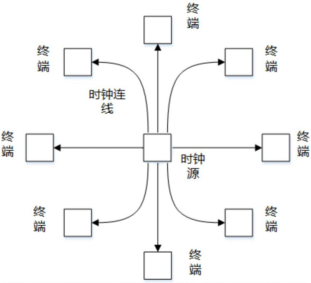
In this way, in a complex system composed of very large-scale terminals, special consideration should be given to clock routing, and a large number of connections will bring difficulties in system assembly, calibration, maintenance, and expansion. Adding a fan-out, which will inevitably require changing the hardware that has been determined, and because in a specific field, such as a scanning imaging system, multiple (several to thousands) detectors (that is, terminals) in it need a unified The time reference is used to meet the global unified clock, and each detector needs a picosecond (ps) level time measurement device so that the entire instrument system requires a higher time resolution, and the accuracy of time synchronization is required to be at the ps level, so for The requirement of line length equal length needs to be at micron (um) level, and the existing global clock design cannot meet this requirement

Method used


Image

  • A method and apparatus for providing a global clock in a system
  • A method and apparatus for providing a global clock in a system
  • A method and apparatus for providing a global clock in a system

Examples


Embodiment Construction

[0048] The present invention will be further described below in conjunction with the embodiments shown in the accompanying drawings.

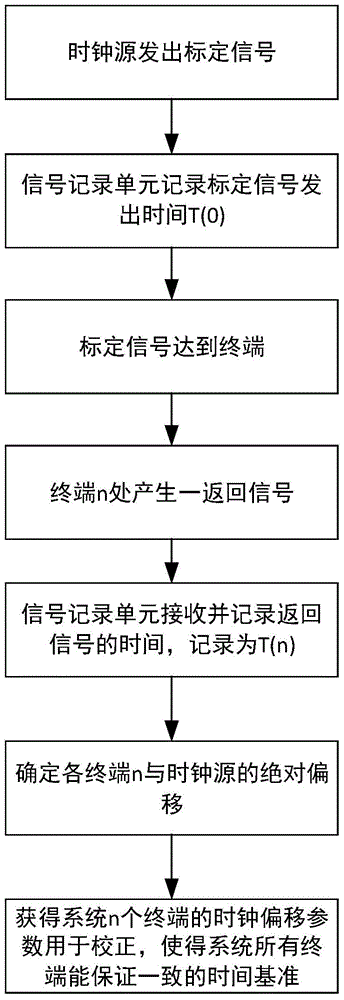
[0049] A method of providing a global clock within the system, such as figure 2 shown, including the following steps:

[0050] Firstly, a reference clock source is determined, and the calibration signal is generated by the reference clock source. There can be multiple clock sources or a uniquely determined clock source in a system. When there are multiple clock sources, it is necessary to determine one of the clock sources as a reference first. The reference clock source can be selected arbitrarily, as long as the clock source can be passed The network transmits to all terminals (that is, covers all terminals). In addition, an external clock source can also be used as a reference clock for the entire system. The above-mentioned clock source can be a clock controller alone or include a clock controller and The clock generator controlled by th...


PUM


Abstract

A method and device for providing a global clock in the system. Terminals in the system are connected by channels, and each terminal is finally connected to a clock source through a signal recording unit. The clock source sends a calibration signal to the network, and the signal recording unit records the calibration signal. At the current sending time T(0), due to the different distances between the clock sources, each terminal will receive the calibration signal in turn and return the signal, and the return signal will return to the signal recording unit successively along the network, and the signal recording unit will then sequentially Record the time T(n) of each return signal, so that the signal recording unit can measure the delay between each terminal and the clock source signal, and use this delay as a correction parameter to ensure that the terminal is in a completely consistent time reference, and this setting is correct The length of the clock connection line from each terminal to the clock source does not need to be controlled, and there is no need to specially consider the clock routing, which avoids the difficulties of system assembly, calibration, maintenance, and expansion caused by a large number of connections.

Description

technical field [0001] The invention belongs to the technical field of time test and measurement, and relates to a method for determining a reference time, in particular to a method for determining a global time. Background technique [0002] The global clock is used in many fields to ensure that all components in the system have exactly the same time reference. For example, in the field of nuclear detection and time-of-flight applications, a system composed of multiple terminals often requires a completely consistent time reference to meet accurate time measurement. . The method of obtaining and correcting communication delay through time stamp communication between multiple terminals is widely used in the field of communication, but this synchronization method is limited to the use of existing communication protocols to achieve global clock synchronization with low precision, such as ms Or sub-ms level, the accuracy of this method ultimately depends on the speed of the cl...

Claims


Application Information

Patent Timeline
Patent Type & Authority Patents(China)
IPC IPC(8): H04L7/00
CPCG06F1/04G06F1/12H04B3/46H04J3/0638H04J3/0682H04L7/10H04L7/0008H04L7/0037
Inventor 房磊张博
Owner THE WUHAN DIGITAL PET CO LTD
Learn More