Method and device for controlling camera for rotation through gesture as well as infrared gesture sensor

A gesture control, infrared gesture technology, applied in the field of control, can solve the problems of wasting power resources, uncertainty, loss of motor mechanical performance, etc., to achieve the effect of improving accuracy

Active Publication Date: 2015-01-28
GUANGDONG OPPO MOBILE TELECOMM CORP LTD
View PDF6 Cites 18 Cited by
  • Summary
  • Abstract
  • Description
  • Claims
  • Application Information

AI Technical Summary

Problems solved by technology

[0003] However, the existing method of controlling the rotation of the camera through an electric motor has many disadvantages
For example, the initial angle of the camera is not known before the rotation, so that it is impossible to determine how much the angle should be rotated to make the camera reach the front, rear or other arbitrary angle positions
In order to accurately reach the position of the front, rear or other arbitrary angles, the existing method usually uses the largest angle of rotation to achieve, thus ensuring that the camera can reach the position of the front, rear or other arbitrary angles. However, this This method is prone to the problem that the camera has been rotated to the end, but the electric motor is still rotating, causing the problem of motor idling, wasting power resources and deteriorating the mechanical properties of the motor
[0004] In addition, there is no method and product in the prior art that combines infrared gesture sensors and digital Hall sensors to realize gesture control camera rotation.

Method used


Image

  • Method and device for controlling camera for rotation through gesture as well as infrared gesture sensor
  • Method and device for controlling camera for rotation through gesture as well as infrared gesture sensor
  • Method and device for controlling camera for rotation through gesture as well as infrared gesture sensor

Examples


Embodiment 1

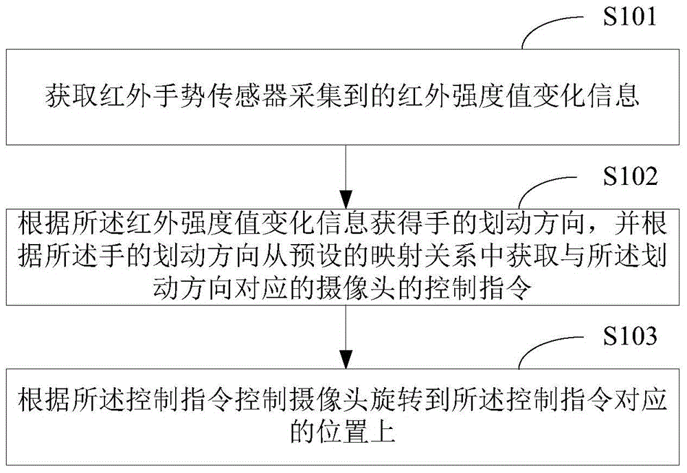
[0060] figure 1 It shows the first implementation flow chart of the method for controlling camera rotation by gestures provided by Embodiment 1 of the present invention; for the convenience of description, only the parts related to the present invention are shown.

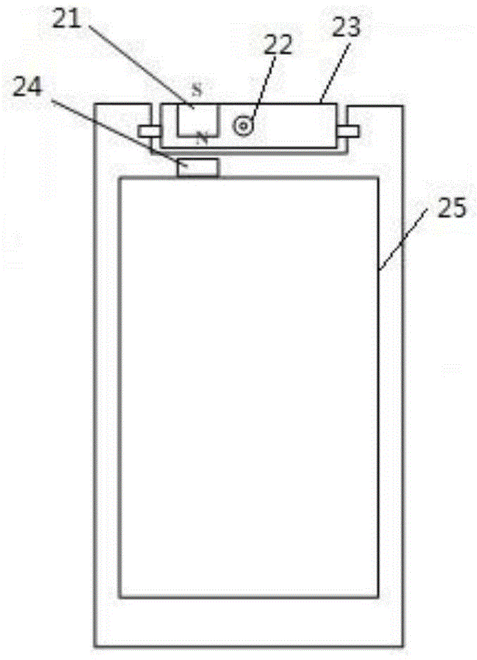
[0061] In this embodiment, the method is applied to user equipment with a rotatable camera, including but not limited to mobile terminals such as mobile phones, tablet computers, and iPads. Wherein, in the rotatable camera, the camera is arranged on a rotatable device, and the rotatable device is located on the mobile terminal; a magnet is arranged on the rotatable device, and the magnet deviates from the rotatable device. The rotating shaft; and the digital Hall sensor is arranged on the main body of the mobile terminal and is arranged opposite to the magnet, which is used to sense the change of the magnetic field caused by the rotation of the magnet with the rotatable device, so as to determine the current offset...

Embodiment 2

[0078] Figure 4 It shows the first implementation process of step S103 in the method for controlling camera rotation with gestures provided by Embodiment 2 of the present invention. For the convenience of description, only the parts related to the present invention are shown.

[0079] When the digital Hall sensor monitors the offset angle of the camera, it is mainly realized by measuring the magnetic induction intensity of the magnet. Such as figure 2 In the structure shown, the distance between the digital Hall sensor and the magnet is the farthest, the magnetic field strength sensed is the weakest, the absolute value of the output value of the digital Hall sensor is the smallest, and the corresponding camera angle is 0 degrees. When the S pole of the magnet rotates to the N pole side, the distance between the digital Hall sensor and the magnet is the shortest, the magnetic field intensity sensed is the strongest, the absolute value of the output value of the digital Hall ...

Embodiment 3

[0094] Image 6 It shows the second implementation process of step S103 in the method for controlling camera rotation by gesture provided in Embodiment 3 of the present invention. For ease of illustration, only the parts relevant to the present invention are shown.

[0095] In this embodiment, the camera control command is to control the camera to rotate to the front position.

[0096] Such as Image 6 As shown, step S103 includes:

[0097] In step S601, the initial output value of the digital Hall sensor is collected.

[0098] In step S602, it is judged whether the initial output value is smaller than a lower threshold.

[0099] Preferably, the lower threshold is the corresponding output value of the digital Hall sensor when the camera angle is 110 degrees. Therefore, when the collected initial output value of the digital Hall sensor is less than the lower threshold, it is determined that the camera is at the rear position, and step S403 is executed.

[0100] In step S6...


PUM


Abstract

The invention is suitable for the field of control technologies and provides a method and device for controlling a camera for rotation through a gesture as well as an infrared gesture sensor. The method comprises the following steps of obtaining infrared intensity value change information collected by the infrared gesture sensor; obtaining a gesturing direction of a hand according to the infrared intensity value change information, and obtaining a control command of the camera, which corresponds to the gesturing direction, from preset mapping relation according to the gesturing direction of the hand; and controlling the camera for rotation on a corresponding position of the control command according to the control command. By adopting the method, the gesturing direction of the hand is induced through the infrared gesture sensor, so that the camera is controlled for rotation at a front position or a rear position through the gesture, and thus accuracy for control is improved, and the problem of easiness in generating idle running of a motor in the existing technology for controlling the camera for rotation is solved.

Description

technical field [0001] The invention belongs to the technical field of control, and in particular relates to a method, a device and an infrared gesture sensor for gesture control camera rotation. Background technique [0002] There are two ways to realize the rotatable camera currently on the market. One is manual rotation. There is no motor on this type of rotatable camera, and the angle of rotation cannot be controlled; the other is automatic rotation. This type of rotatable camera has a built-in electric motor, which can be controlled by controlling the rotation of the electric motor through a control chip. The angle by which the camera is rotated. [0003] However, the existing method of controlling the rotation of the camera by an electric motor has many disadvantages. For example, the initial angle of the camera is not known before the rotation, so that it is impossible to determine how much the angle should be rotated to make the camera reach the front, rear or othe...

Claims


Application Information

Patent Timeline
Patent Type & Authority Applications(China)
IPC IPC(8): H04N5/232G06F3/01
Inventor 张强
Owner GUANGDONG OPPO MOBILE TELECOMM CORP LTD
Why Eureka
Try Eureka