Unlock instant, AI-driven research and patent intelligence for your innovation.
A beater blade structure
What is Al technical title?
Al technical title is built by PatSnap Al team. It summarizes the technical point description of the patent document.
A blade structure and beater technology, applied in mixers, mixer accessories, dissolving and other directions, can solve the problems of complex blade structure, high manufacturing cost, difficult to clean, etc., and achieve the effect of improving beating rate, simple structure, and preventing dead ends of beating.
Active Publication Date: 2016-04-06
ZHEJIANG WUXIAN NEW ENERGY
View PDF7 Cites 0 Cited by
Summary
Abstract
Description
Claims
Application Information
AI Technical Summary
This helps you quickly interpret patents by identifying the three key elements:
Problems solved by technology
Method used
Benefits of technology
Problems solved by technology
[0003] In order to further improve the beating quality, the designers often design the blade structure more complicated, resulting in the disadvantage of not being easy to clean, and the manufacturing cost is higher
Method used
Image
Click on the blue label to locate the original text in one second.
Reading with bidirectional positioning of images and text.
Examples
Embodiment 1
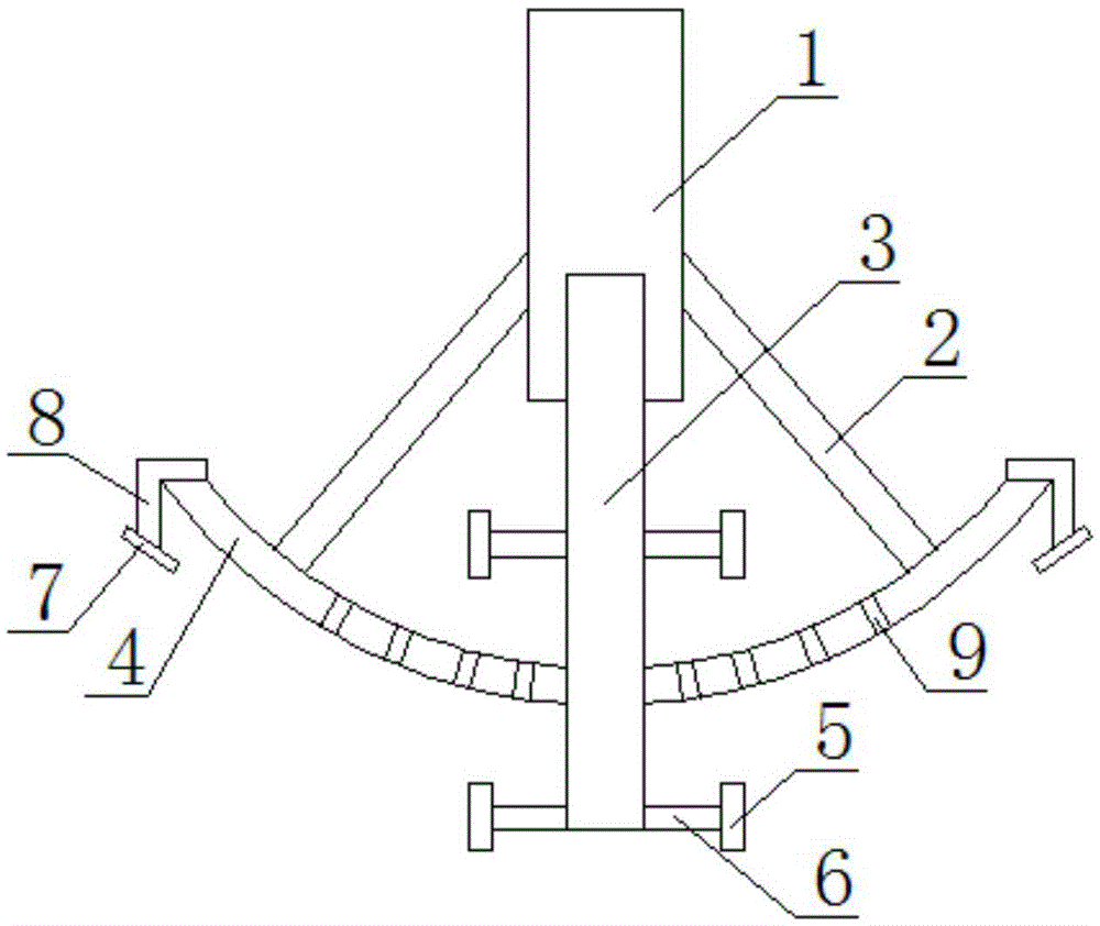
[0019] Such as figure 1 As shown, a beater blade structure includes an outer shaft 1, a connecting rod 2, an inner shaft 3, a main blade 4, a secondary blade 5, a connector 6, a guide plate 7 and a guide plate connecting seat 8;
[0020] One end of the outer shaft 1 is provided with an internal threaded hole along the central axis, one end of the inner shaft 3 is provided with an external thread, the inner shaft 3 is sleeved in the outer shaft 1, and the outer shaft 1 and the inner shaft 3 are connected by threads;
[0021] The main blade 4 is an arc-shaped sheet structure, the middle of the main blade 4 is provided with a through hole, the inner shaft 3 is sleeved in the through hole of the main blade 4, and the through hole diameter of the main blade 4 matches the rod diameter of the inner shaft 3 , The outer shaft 1 is connected with the inner arc surface of the main blade 4 through the connecting rod 2; the main blade 4 can also be provided with a number of filter holes 9 which ...
Embodiment 2
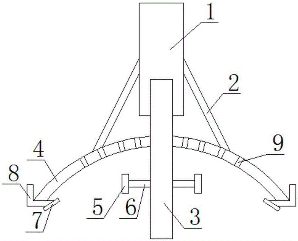
[0025] Such as figure 2 As shown, a beater blade structure includes an outer shaft 1, a connecting rod 2, an inner shaft 3, a main blade 4, a secondary blade 5, a connector 6, a guide plate 7 and a guide plate connecting seat 8;
[0026] One end of the outer shaft 1 is provided with an internal threaded hole along the central axis, one end of the inner shaft 3 is provided with an external thread, the inner shaft 3 is sleeved in the outer shaft 1, and the outer shaft 1 and the inner shaft 3 are connected by threads;
[0027] The main blade 4 is an arc-shaped sheet structure, the middle of the main blade 4 is provided with a through hole, the inner shaft 3 is sleeved in the through hole of the main blade 4, and the through hole diameter of the main blade 4 matches the rod diameter of the inner shaft 3 , The outer shaft 1 is connected with the outer arc surface of the main blade 4 through the connecting rod 2; the main blade 4 can also be provided with a number of filter holes 9 and ...
PUM
Abstract
The invention provides a blade structure of a beating machine. The blade structure comprises an outer shaft rod, connecting rods, an inner shaft rod, a main blade, auxiliary blades and connecting pieces, wherein the inner shaft rod is sheathed in the outer shaft rod which is in threaded connection with the inner shaft rod; the main blade is of an arc-shaped flaky structure; a through hole is formed at the position of the middle part of the main blade; the inner shaft rod is sheathed in the through hole of the main blade; the outer shaft rod is connected with the inner arc surface of the main blade by the connecting rods; and the auxiliary blades are connected with the inner shaft rod by the connecting pieces. The blade structure provided by the invention has the advantages and the positive effects that by ingenious structure design, the problems that the beating quality of the beating machine adopting simple blades is poor and the beating machine adopting complex blades is inconvenient to clean and maintain and is low in blade manufacturing cost and the like in the prior art are solved; and the blade structure provided by the invention is sufficient in beating, high in beating speed, simple in structure and convenient in blade cleaning and maintenance.
Description
Technical field [0001] The invention belongs to the technical field of beaters, and particularly relates to a blade structure of a beater. Background technique [0002] Beater is a kind of equipment that mixes color paste, original paste, cosolvent and other chemical additives together and stirs them evenly. The blade structure is an important part related to the quality of beating. [0003] In order to further improve the beating quality, designers often design the blade structure to be more complicated, which causes the disadvantages of difficult cleaning and higher manufacturing costs. Summary of the invention [0004] The purpose of the present invention is to provide a beater blade structure that is easy to clean, high in mixing efficiency, and excellent in mixing quality in view of the shortcomings of the prior art. [0005] In order to solve the above technical problems, the technical solution adopted by the present invention is: a beater blade structure, including outer shaft...
Claims
Application Information
Patent Timeline
Application Date:The date an application was filed.
Publication Date:The date a patent or application was officially published.
First Publication Date:The earliest publication date of a patent with the same application number.
Issue Date:Publication date of the patent grant document.
PCT Entry Date:The Entry date of PCT National Phase.
Estimated Expiry Date:The statutory expiry date of a patent right according to the Patent Law, and it is the longest term of protection that the patent right can achieve without the termination of the patent right due to other reasons(Term extension factor has been taken into account ).
Invalid Date:Actual expiry date is based on effective date or publication date of legal transaction data of invalid patent.

