
Hub bearing unit equipped with a low friction sealing assembly

一种轮毂轴承、密封组件的技术,应用在轴承元件、旋转运动的轴承、轮毂等方向,能够解决组装工作难、复杂形状增加成本、增加体积等问题

Active Publication Date: 2015-02-04
AB SKF
View PDF9 Cites 12 Cited by
  • Summary
  • Abstract
  • Description
  • Claims
  • Application Information

AI Technical Summary

Problems solved by technology

[0004] In addition, the complex shape of the cage increases the cost, makes the assembly work more difficult and, most importantly, increases the volume considerably, especially in the axial direction of the sealing assembly

Method used


Image

  • Hub bearing unit equipped with a low friction sealing assembly
  • Hub bearing unit equipped with a low friction sealing assembly

Examples


Embodiment Construction

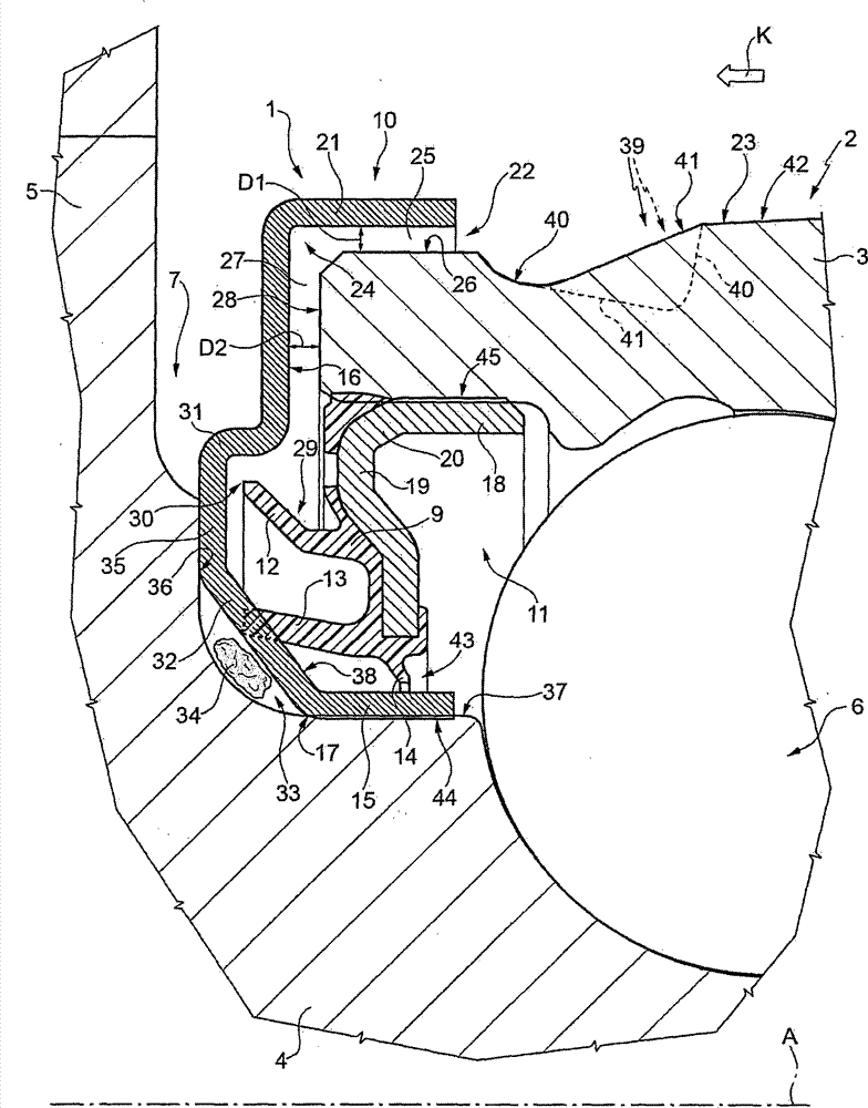
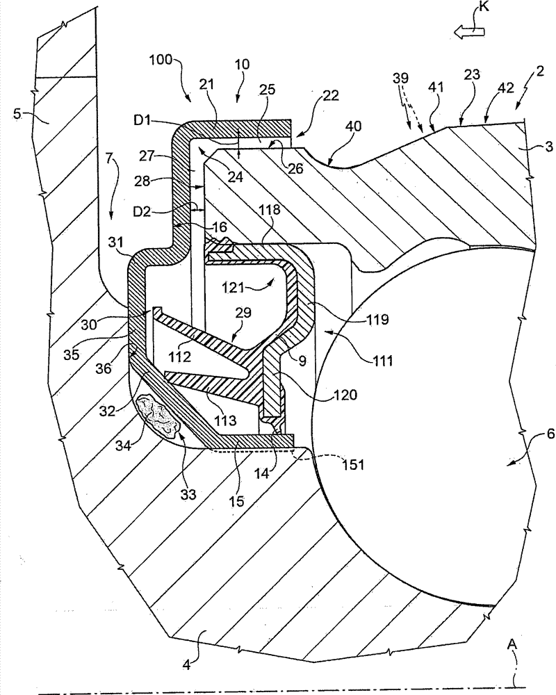
[0013] figure 1 The number 1 in refers to a low-friction sealing assembly, especially designed to be mounted on a hub bearing unit 2 of a vehicle, in which the sealing assembly 1 is integrated in use.

[0014] A hub bearing unit 2 of known type comprises an outer ring 3 fixed in use, an inner ring 4 rotating in use about an axis A, and at least the tops of rolling bodies 6 inserted between the outer ring 3 and inner ring 4, axis A Also the axis of symmetry of the rings 3 and 4, which are coaxial with each other, the ring 4 has a flanged end 5 opposite to the outer ring 3 and serves to carry the wheel.

[0015] The seal assembly 1 is inserted into the annular gap 7 defined between the fixed outer ring 3 and the rotating inner ring 4 of the hub bearing 2, and more particularly, between the coaxial rotating part 4 and the fixed part 3 of a universal rolling bearing of known type Between them, they are a part of the hub bearing 2 or integrated with it.

[0016] The seal assembly...


PUM


Abstract

An assembly providing a first annular shield including a sleeve portion integral with a rotating member and with a flange portion, which radially extends to protrude from the first sleeve portion; a second annular shield having a sleeve portion integral with a stationary member and with a flange portion that radially extends to protrude on the opposite side of the sleeve portion of the first shield and facing the flange portion; and an annular seal, which the flange portion of the first shield ends with an L-shaped annular portion that protrudingly radially and axially extends out of an annular gap delimited between the rotating and stationary members to define an L-shaped channel in radial section having constant width and forming a first labyrinth seal; the channel leads into an annular recess, delimited between the second shield and a first lip of the annular seal without contacting the first shield.

Description

technical field [0001] The invention relates to a hub bearing unit with a low-friction sealing assembly, in particular a rolling bearing for mounting a vehicle hub bearing unit. Background technique [0002] The seal assembly for mounting the rolling bearings of a hub bearing assembly on the side of the flange supporting the wheel, the "outside", such as disclosed in US8303190 and US2012 / 0177315, consists of a so-called "cassette" seal comprising First and second annular shrouds, generally L-shaped in the radial direction, are mounted facing each other so as to define between the shrouds an annular cavity in which a series of sealing lips are disposed by annular sealing, and An annular seal is integrally fixed to one of the covers, which generally serve to keep it stationary. The entry of external contamination (water, mud, dust) into the cavity is limited due to the special construction of the flange part of the two housings or one of them, which is also in a very tight ma...

Claims


Application Information

Patent Timeline
Patent Type & Authority Applications(China)
IPC IPC(8): F16C33/80
CPCF16C33/805F16J15/3252F16C2326/02F16J15/324F16C33/7879F16C19/184F16C33/783F16J15/4472F16C19/04F16J15/3456F16J15/4476B60B27/0073B60B2900/5112B60B2900/5114F16C33/7826F16C33/586Y02T10/86
Inventor D·达克F·莫雷罗A·塞拉菲尼
Owner AB SKF
Learn More