Water energy circulation stove water heater

A technology for water heaters and earth stoves, which is applied to stoves/stoves with hot water devices, household heating, heating methods, etc., can solve the problems of poor circulation loop fluidity and inability to adjust the outlet water temperature, and achieve the effect of promoting circulation

Inactive Publication Date: 2015-02-04
ZHEJIANG PROVINCE INST OF ARCHITECTURAL DESIGN & RES
View PDF6 Cites 7 Cited by
  • Summary
  • Abstract
  • Description
  • Claims
  • Application Information

AI Technical Summary

Problems solved by technology

[0004] The invention provides a water energy circulation earth stove water heater which is convenient for replenishing water, the temperature of the outlet water can be adjusted, and the water energy of the tap water can be used to promote the circulation when draining water. The problem of poor fluidity of the circulation loop when regulating and draining

Method used


Image

  • Water energy circulation stove water heater
  • Water energy circulation stove water heater
  • Water energy circulation stove water heater

Examples


Embodiment 1

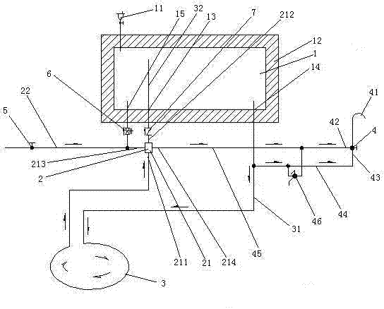
[0035] Embodiment one, see figure 1 What is claimed is an earthen stove water heater with water energy circulation, comprising a water tank 1, a circulation promoter 2, a heat exchange coil 3 and a shower faucet 4.

[0036] The top wall of the water tank 1 is provided with an exhaust valve 11 . The outside of the water tank 1 is wrapped with an insulating layer 12 . The bottom wall of the water tank 1 is provided with a circulating water inlet 13 , a circulating water outlet 14 and a pressure relief port 15 .

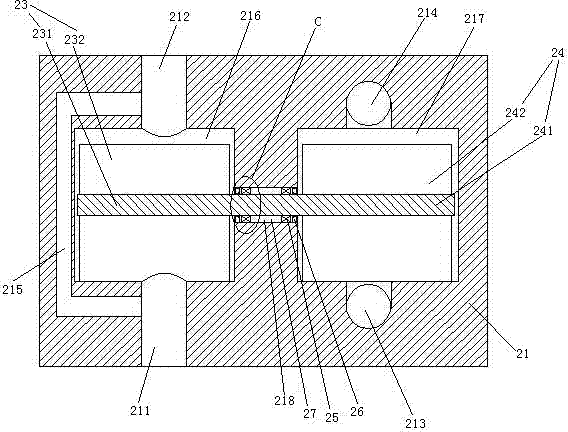
[0037] The circulation booster 2 includes a housing 21 . The casing 21 is provided with a first water inlet 211 , a first water outlet 212 , a second water inlet 213 and a second water outlet 214 . The second water inlet 213 is connected with the cold water inlet pipe 22 . The cold water inlet pipe 22 is provided with a stop valve 5 . A check safety valve 6 is provided between the cold water inlet pipe 22 and the pressure relief port 15 . The outlet end of check s...

Embodiment 2

[0044] Embodiment two, the difference with embodiment one is:

[0045] see Figure 4 , The bottom of the water tank 1 is provided with a rubber pad 8. There are four rubber pads 8.

[0046] see Figure 5 , The bottom surface of the rubber pad 8 is provided with a liquid storage cavity 81 . An isolation plate 82 is provided in the liquid storage chamber 81 . The isolation plate 82 divides the liquid storage chamber 81 into an upper liquid storage chamber 811 and a lower liquid storage chamber 812 . The lower end of the lower liquid storage chamber 812 is provided with a rubber cover 83 . The rubber cover 83 is in the shape of a bowl arched towards the inside of the lower liquid storage chamber 812 . A skeleton 84 is arranged inside the rubber pad 8 . The frame 84 is a coil spring that expands and contracts in the vertical direction. The liquid storage cavity 81 is located inside the space surrounded by the skeleton 84 . The isolation plate 82 is provided with several m...

Embodiment 3

[0050] Embodiment three, the difference with embodiment two is:

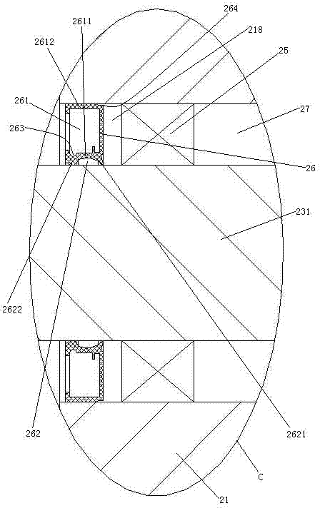
[0051] see Figure 8 , also includes oil replenishment mechanism 9. The shaft hole 218 is also provided with an oil filling hole 219 . The outlet end of the oil filling hole 219 is located in the sealed cavity 27 . The oil replenishing mechanism 9 includes an oil storage tank 91 , an oil outlet channel 92 and a corrosive liquid storage tank 94 .

[0052] One end of the oil outlet passage 92 is provided with a filler nozzle 922 , and the other end is provided with an oil inlet bucket 921 . The filler nozzle 922 is butted together with the filler hole 219 . The oil inlet hopper 921 is located below the oil storage tank 91 . The filler nozzle 922 is lower than the oil storage tank 91 , that is, the oil in the oil outlet channel 92 can automatically flow into the filler nozzle 922 and enter the sealed cavity 27 .

[0053] The corrosive liquid storage tank 94 is connected with the variable casing 21 together. ...


PUM


Abstract

The invention relates to a stove water heater, and solves the problems that a water tank of the stove water heater needs to be manually replenished with water, the effluent temperature cannot be adjusted and the fluidity of a circulating loop is poor during drainage. A water energy circulation stove water heater has the advantages of convenience in water replenishing, adjustability of the effluent temperature and promotion of circulation by using water energy of tap water during drainage. The water energy circulation stove water heater comprises a shower faucet, a circulation promoter and a circulating loop consisting of a water tank and a heat exchange coil, wherein the shower faucet is provided with a cold water inlet and a hot water inlet; the circulation promoter comprises a shell; the shell is provided with a first impeller chamber and a second impeller chamber which are isolated from each other; the first impeller chamber is provided with a first water inlet, a first water outlet and a first impeller; the second impeller chamber is provided with a second water inlet, a second water outlet and a second impeller; the second water outlet is connected with the cold water inlet; the hot water inlet is connected with the circulating loop; a mixed water faucet is arranged between the cold water inlet and the hot water inlet; the first impeller chamber and the heat exchange coil are connected together in series.

Description

technical field [0001] The invention relates to an earthen stove water heater, in particular to an earthen stove water heater with water energy circulation. Background technique [0002] The earth stove water heater is a water heater that uses the heat emitted by the earth stove to heat the water, and has the advantage of not consuming electricity, gas and other energy sources. A kind of soil stove water heater is disclosed in the patent document whose Chinese patent number is 2009201265540, the date of authorization announcement is December 16, 2009, and the name is called "earth stove water heater". The earth stove water heater in this patent document includes a water tank and a heat exchange coil for absorbing the heat of the earth stove. The two ends of the heat exchange coil are connected with the water tank to form a circulation loop, and the water outlet tap is provided on the circulation loop. When in use, the heat exchange coil is buried in the soil stove, and wate...

Claims


Application Information

Patent Timeline
Patent Type & Authority Applications(China)
IPC IPC(8): F24B9/00
Inventor 钱杰蒋纹郑军叶欣
Owner ZHEJIANG PROVINCE INST OF ARCHITECTURAL DESIGN & RES
Why Eureka
Try Eureka