[0025] The present invention will be described in detail below in conjunction with the embodiments shown in the drawings. However, these embodiments do not limit the present invention, and the structural, method, or functional changes made by those skilled in the art based on these embodiments are all included in the protection scope of the present invention.
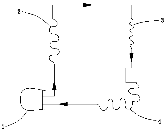
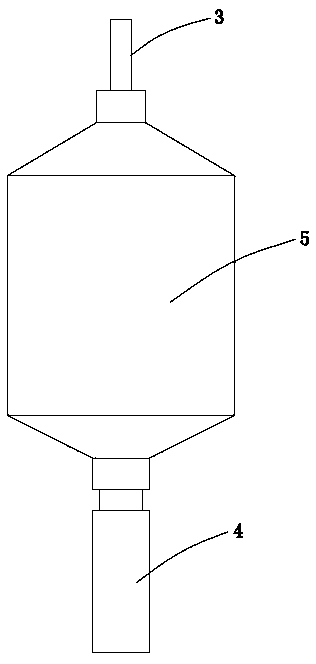
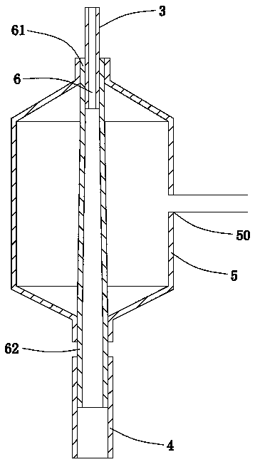
[0026] Please refer to Figure 1 to Figure 5 The refrigerator refrigeration system 100 of the present invention includes a compressor 1, a condenser 2, a capillary tube 3, and an evaporator 4 connected in sequence, and the output end of the evaporator 4 is connected to the input end of the compressor 1, thereby forming the refrigerator refrigeration system 100 of the present invention. The circulation path of the refrigerant. Due to the joint action of the compressor 1 and the capillary tube 3, the high pressure in the condenser 2 and the low pressure in the evaporator 4 can be maintained. When the refrigerant flows from the high-pressure condenser 2 into the low-pressure evaporator 4 through the capillary tube 3, it will flow in the capillary tube 3. The end and the evaporator 4 vaporize and absorb heat to achieve the purpose of refrigeration.
[0027] The refrigerator refrigeration system 100 of the present invention further includes a muffler 5 and a diverging tube 6 arranged between the capillary tube 3 and the evaporator 4. The divergent tube 6 has a hollow tubular shape and includes a first end 61 with a smaller diameter and a second end 62 with a larger diameter opposite to the first end 61. The outlet end of the capillary tube 3 is inserted into the first end 61 of the expanding tube 6 and welded, and the second end 62 of the expanding tube 6 is inserted into the inlet end of the evaporator 4 and welded, wherein the outer diameter of the capillary tube 3 The inner diameter of the first end 61 of the divergent tube 6 is equal to that of the second end 62 of the divergent tube 6 and the inner diameter of the inlet end of the evaporator 4 is the same. The muffler 5 is arranged on the outside of the divergent tube 6, and is shaped like figure 2 with image 3 As shown, one end of the muffler 5 is aligned with and welded to the divergent tube 6, and the other end is also welded to the divergent tube 6 and evacuated to form a vacuum layer 7 between the divergent tube 6 and the muffler 5.
[0028] The contact part of the capillary tube 3 and the muffler 5 needs to be welded. At the same time, the capillary tube 3 also needs to be welded to the expanding tube 6. The length of the capillary tube 3 inserted into the expanding tube 6 is 10mm to ensure that the capillary tube 3 and the muffler 5, gradually The welding between the expansion tubes 6 is firm.
[0029] The role of the diverging tube 6 is to reduce the impact of the refrigerant at the inlet end of the evaporator 4. By setting the diverging tube 6, the refrigerant coming out of the capillary tube 3 starts to expand steadily. When the refrigerant reaches the inlet end of the evaporator 4, the speed decreases. The diameter difference is reduced, so that the impact strength is reduced, the pipeline vibration is reduced, and the radiated noise is also reduced.
[0030] After multiple measurements and analysis, the noise level is the highest at the first expansion. Therefore, the area covered by the muffler 5 is the first eruption of the refrigerant and its extension.
[0031] A vacuum layer 7 is formed between the divergent tube 6 and the muffler 5. The specific realization method of the vacuum layer 7 is: the muffler 5 is provided with a vacuum port 50, and a vacuum pump (not shown) is connected to the muffler 5 through a thin tube After the vacuuming port 50 is completed, the vacuum port 50 is sealed to prevent air from entering. The noise generated by the refrigerant in the diverging tube 6 is cut off due to the cut off and cannot be transmitted through the vacuum layer 7 so as to eliminate the noise to the maximum extent.
[0032] Please refer to Figure 4 with Figure 5 As shown, in the manufacturing process, for manufacturing convenience, the muffler 5'can also be divided into two parts along the extending direction of the divergent tube 6', that is, the muffler 5'includes a left vacuum chamber 51' and a right vacuum chamber that are isolated from each other 52', the left vacuum chamber 51' and the right vacuum chamber 52' are formed by welding the muffler 5'and the expanding tube 6'along the extending direction of the expanding tube 6', and the welding place 56' is such as Figure 4 Shown.
[0033] The refrigerator refrigeration system 100 of the present invention can minimize the injection noise at the interface between the capillary tube 3 and the evaporator 4, and improve customer satisfaction.
[0034] It should be understood that although this specification is described in accordance with the implementation manners, not each implementation manner only contains an independent technical solution. This narration in the specification is only for clarity, and those skilled in the art should consider the specification as a whole. The technical solutions in each embodiment can also be appropriately combined to form other embodiments that can be understood by those skilled in the art.