Blind element detection method and device of infrared focal plane array

A technology of infrared focal plane and detection method, applied in measuring devices, radiation pyrometry, optical radiation measurement, etc., can solve problems such as poor stability, achieve low storage overhead, ensure fast implementation, and simple operation

Active Publication Date: 2018-03-23
凯迈(洛阳)测控有限公司
View PDF4 Cites 2 Cited by
  • Summary
  • Abstract
  • Description
  • Claims
  • Application Information

AI Technical Summary

Problems solved by technology

[0006] The purpose of the present invention is to provide a blind element detection method of an infrared focal plane array to solve the problem of poor stability of the existing blind element detection method

Method used


Image

  • Blind element detection method and device of infrared focal plane array
  • Blind element detection method and device of infrared focal plane array
  • Blind element detection method and device of infrared focal plane array

Examples


Embodiment 1

[0039] The basic scheme of the blind element detection method of infrared focal plane array is as follows:

[0040] Initialization step: Power on the infrared system and block the light path;

[0041] Sequential acquisition steps: each acquisition of a frame of detector raw image data I t , t is currently the number of acquisitions;

[0042]Processing steps after each acquisition: After each acquisition, add a window to each pixel as the center in turn, and calculate the local mean value μ of the pixels in the neighborhood of the set range of the pixel local and the local standard deviation σ local , if the pixel and the local mean μ local The difference is greater than three times the local standard deviation σ local , the pixel is counted correspondingly; at the same time, the original image data It is superimposed;

[0043] Blind element judgment step: After collecting T times, the corresponding count value of the pixel is counted, and if the corresponding count value ...

Embodiment 2

[0047] The infrared imaging system adopted in this embodiment can use a medium-wave cooled focal plane array detector with an area array size of 320×256. The image processing circuit of the imaging system is composed of FPGA and DSP, and the FPGA performs the processing of the original image data of the detector. Collection, the distribution range of data is [-32768, 32767], DSP performs subsequent processing, and the blind element detection process is implemented in DSP.

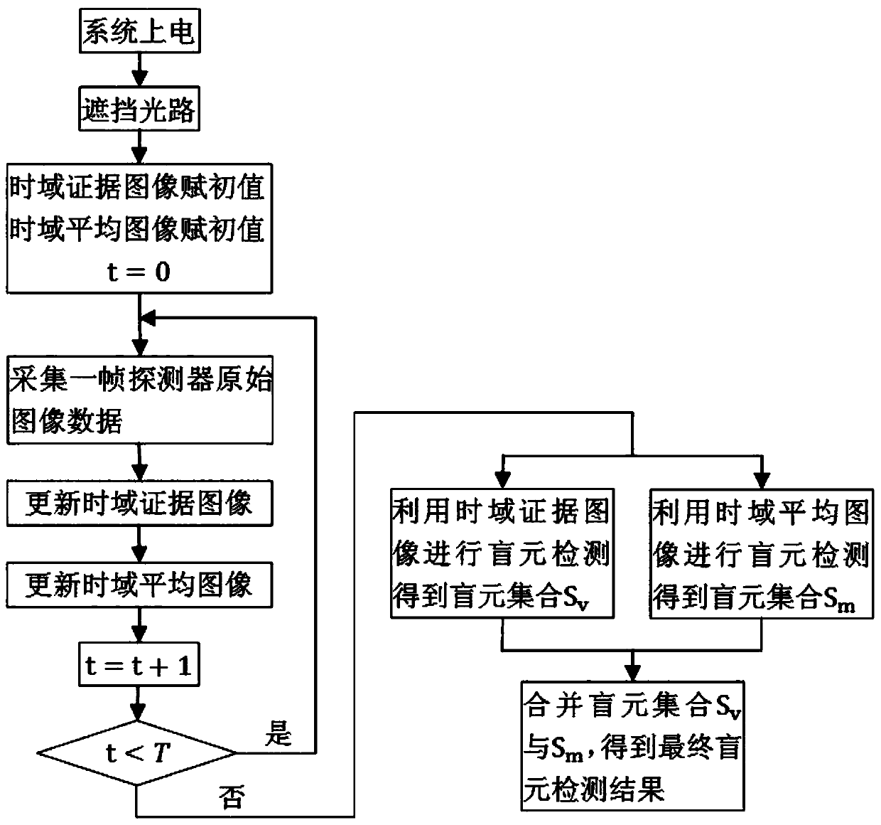
[0048] refer to figure 1 , the specific implementation steps of the whole embodiment are as follows:

[0049] Step 1: After the infrared imaging system is powered on, the light path is blocked by command control shutter.

[0050] Step 2, assign an initial value to the time-domain evidence image, namely E v (i, j)=0, assign an initial value to the time-domain average image, namely E m (i, j)=0, (i, j) is the pixel coordinates, the initial value is assigned to the loop count, that is, t=0, then, the loop s...


PUM


Abstract

The invention relates to a blind element detection method and device of an infrared focal plane array, which is used to solve the problem of poor stability of the existing blind element detection method. When judging the blind pixels, the present invention utilizes the characteristic that the gray value of the infrared image based on the uniform background is close to the normal distribution, adds a window and calculates with the pixel as the center. The accuracy rate of this scheme is poor. Through research, we found that this is caused by noise interference. Therefore, on this basis, one frame of the original image of the detector is collected each time, and the calculation results are statistically judged in the time domain. By setting the evidence threshold, the false blind detection caused by noise can be effectively avoided, and the detection accuracy can be improved. .

Description

technical field [0001] The invention relates to a blind element detection method and device of an infrared focal plane array. Background technique [0002] Affected by factors such as materials and manufacturing processes at the present stage, invalid pixels generally exist in infrared focal plane array detectors, and these invalid pixels are also called blind pixels. If no corresponding processing is performed during imaging, blind pixels will cause bright or dark spots to appear in the corresponding positions of the infrared image, which will seriously affect the quality of infrared imaging. Therefore, compensation for blind pixels is not possible in infrared imaging. a missing link. However, the premise and foundation of blind pixel compensation is to be able to detect blind pixels effectively. Therefore, an efficient blind pixel detection method is of great significance for improving the quality of infrared imaging. [0003] At present, it is a common method to detect ...

Claims


Application Information

Patent Timeline
Patent Type & Authority Patents(China)
IPC IPC(8): G01J5/02
Inventor 吴明军郑逢勋赵新亮马向华陈峥
Owner 凯迈(洛阳)测控有限公司
Why Eureka
Try Eureka