A high-precision pulse power detection module

A pulse power and detection module technology, which is applied in the direction of measuring electric power, measuring devices, and measuring electrical variables, etc., can solve the problems of heavy weight, high false alarm rate, and large detection module volume, and achieve high accuracy and low false alarm rate , small size effect

Active Publication Date: 2017-10-31
ANHUI SUN CREATE ELECTRONICS
View PDF5 Cites 0 Cited by
  • Summary
  • Abstract
  • Description
  • Claims
  • Application Information

AI Technical Summary

Problems solved by technology

Existing detection modules are too large in size and heavy in weight, unable to effectively resist the interference of external power supply voltage fluctuations, and easily cause a high false alarm rate

Method used


Image

  • A high-precision pulse power detection module
  • A high-precision pulse power detection module
  • A high-precision pulse power detection module

Examples


Embodiment Construction

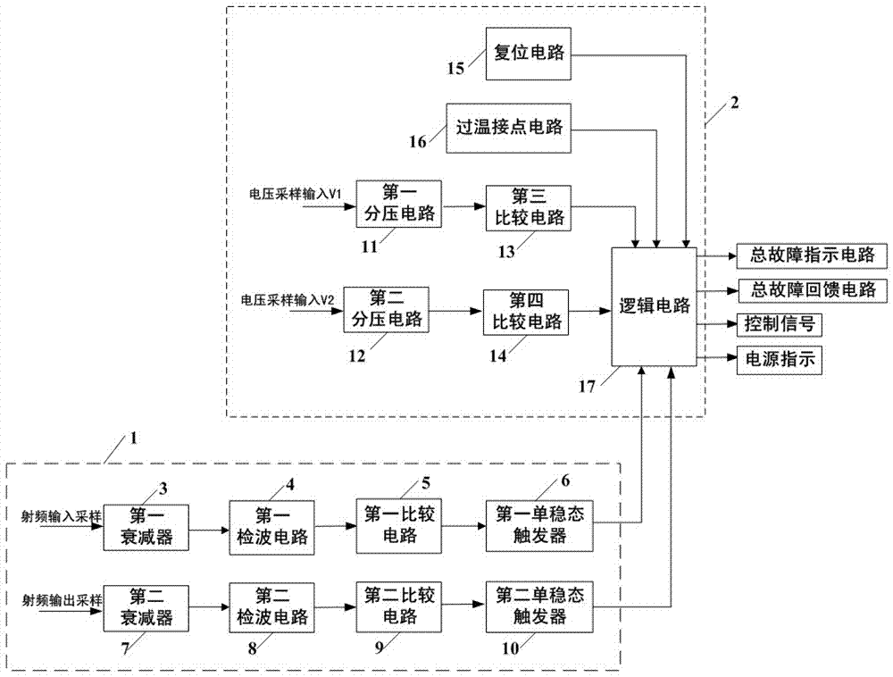
[0015] A high-precision pulse power detection module, including a radio frequency circuit 1 for receiving radio frequency input sampling signals and radio frequency output sampling signals, the output terminal of radio frequency circuit 1 and the input of detection circuit 2 for receiving sampling voltage V1 and sampling voltage V2 The output terminal of the detection circuit 2 is connected with the fault indication circuit, such as figure 1 shown.

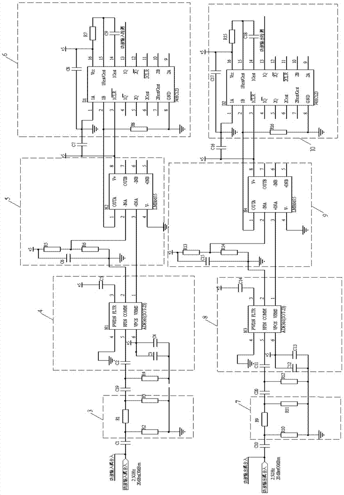
[0016] Such as figure 1 As shown, the radio frequency circuit 1 is composed of a first attenuator 3, a second attenuator 7, a first detection circuit 4, a second detection circuit 8, a first comparison circuit 5, a second comparison circuit 9, a first monostable The trigger 6 and the second monostable trigger 10 are composed, the input terminal of the first attenuator 3 is connected to the radio frequency input sampling signal, and the output terminal of the first attenuator 3 passes through the first detection circuit 4, the fir...


PUM


Abstract

The invention relates to a high-precision pulse power detection module, which includes a radio frequency circuit for receiving radio frequency input sampling signals and radio frequency output sampling signals, the output end of the radio frequency circuit and the input of the detection circuit for receiving sampling voltage V1 and sampling voltage V2 The output terminal of the detection circuit is connected with the fault indication circuit. The present invention can simultaneously detect the over-temperature contact, voltage V1 sampling, voltage V2 sampling, radio frequency input sampling, and radio frequency output sampling, and can monitor the input and output power changes of the front-stage components in real time, and then accurately judge whether the input power and output power are faulty, It can monitor the stability of the voltage in real time, and then accurately judge whether it is an undervoltage state caused by a voltage drop, resulting in no power output, which can effectively and quickly find the cause of the fault and facilitate maintenance.

Description

technical field [0001] The invention relates to the technical field of radar detection, in particular to a high-precision pulse power detection module. Background technique [0002] With the rapid development of electronic technology, while the radar function is perfect, it also increases the complexity of radar technology, making it more dependent on the internal inspection equipment (BITE) in maintenance. With the development of the detection module, the fault location time, which accounts for the main share of the maintenance time, is greatly shortened. Fault detection technology is mainly to study how to find the fault location early and quickly eliminate the fault. It has an online detection function and can quickly and accurately locate the fault. Existing detection modules are too large in size and heavy in weight, which cannot effectively resist the interference of external power supply voltage fluctuations, and easily cause high false alarm rates. With the complex...

Claims


Application Information

Patent Timeline
Patent Type & Authority Patents(China)
IPC IPC(8): G01R21/00G01S7/40
Inventor 王腾飞孙伟毛飞唐进冉亮
Owner ANHUI SUN CREATE ELECTRONICS
Why Eureka
Try Eureka