Splicing seam brightness compensation and adjustment method for high-density LED display screen

A technology of LED display and brightness compensation, which is applied to static indicators, instruments, etc., can solve problems such as increasing display manufacturing costs, uneven brightness distribution, and affecting screen display effects, so as to improve display effects, avoid errors, and improve Effect of Positioning Accuracy and Efficiency

Active Publication Date: 2015-02-04
CHANGCHUN CEDAR ELECTRONICS TECH CO LTD
View PDF6 Cites 21 Cited by
  • Summary
  • Abstract
  • Description
  • Claims
  • Application Information

AI Technical Summary

Problems solved by technology

In addition, due to the fact that the two sides of the patchwork are not parallel, the brightness distribution of the bright and dark lines themselves is not uniform, which affects the display effe

Method used


Image

  • Splicing seam brightness compensation and adjustment method for high-density LED display screen
  • Splicing seam brightness compensation and adjustment method for high-density LED display screen
  • Splicing seam brightness compensation and adjustment method for high-density LED display screen

Examples


Example Embodiment

[0045] Example 1

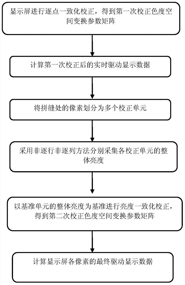
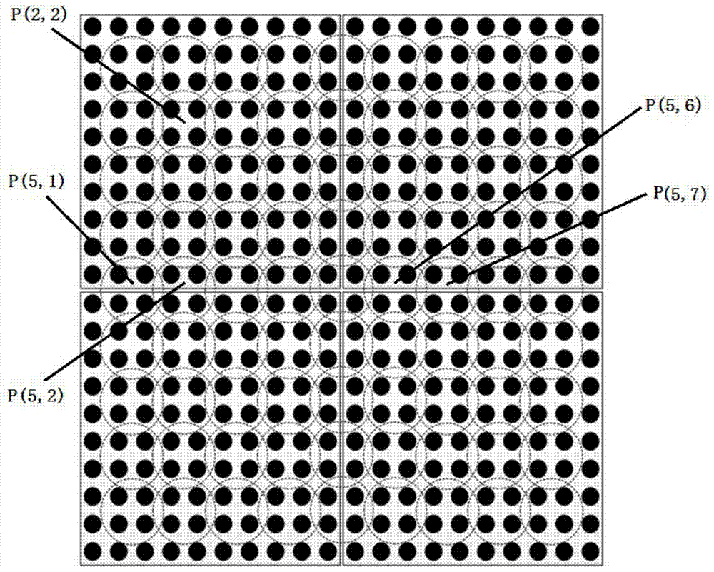
[0046] Such as figure 2 As shown, the high-density LED display screen of the present invention is an integrated display screen with a dot pitch d=2.5mm. The process of the brightness compensation adjustment method of the high-density LED display screen is as follows:

[0047] Firstly, perform the point-by-point brightness and color uniformity correction on the display screen to obtain the first correction chromaticity space transformation parameter matrix of each pixel;

[0048] N [ m , n ] [ i , j ] _ 1 = C [ m , n ] [ i , j ] _ 1 rr C [ m , n ] [ i , j ] _ 1 rg C [ m , n ] [ i , j ] _ 1 rb C [ m , n ] [ i , j ] _ 1 gr C [ m , n ] [ i , j ] _ 1 gg C [ m , n ] [ i , j ] _ 1 gb C [ m , n ] [ i ...

Example Embodiment

[0057] Example 2

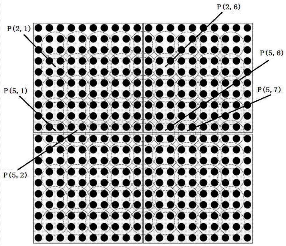
[0058] Such as image 3 As shown, the high-density LED display screen of the present invention is an integrated display screen with a dot pitch d=1.875 mm. The process of the brightness compensation adjustment method of the high-density LED display screen is as follows:

[0059] Firstly, perform the point-by-point brightness and color uniformity correction on the display screen to obtain the first correction chromaticity space transformation parameter matrix of each pixel;

[0060] N [ m , n ] [ i , j ] _ 1 = C [ m , n ] [ i , j ] _ 1 rr C [ m , n ] [ i , j ] _ 1 rg C [ m , n ] [ i , j ] _ 1 rb C [ m , n ] [ i , j ] _ 1 gr C [ m , n ] [ i , j ] _ 1 gg C [ m , n ] [ i , j ] _ 1 gb C [ m , n ] [ ...

Example Embodiment

[0069] Example 3

[0070] Such as Figure 4 As shown, the high-density LED display screen of the present invention is an integrated display screen with dot pitch d=1.25mm. The process of the brightness compensation adjustment method of the high-density LED display screen is as follows:

[0071] Firstly, perform the point-by-point brightness and color uniformity correction on the display screen to obtain the first correction chromaticity space transformation parameter matrix of each pixel;

[0072] N [ m , n ] [ i , j ] _ 1 = C [ m , n ] [ i , j ] _ 1 rr C [ m , n ] [ i , j ] _ 1 rg C [ m , n ] [ i , j ] _ 1 rb C [ m , n ] [ i , j ] _ 1 gr C [ m , n ] [ i , j ] _ 1 gg C [ m , n ] [ i , j ] _ 1 gb C [ m , n ] [ i ...


PUM


Abstract

The invention relates to a splicing seam brightness compensation and adjustment method for a high-density LED display screen. The method comprises the following steps: conducting point-by-point consistency correction to obtain the first-correction color space conversion parameter matrixes of pixels; partitioning the pixels in a splicing seam area into a plurality of correction units; driving the correction units and benchmark units in modules to conduct display via real-time drive display data obtained after the first correction; conducting brightness consistency correction on the correction units by taking the brightness of the benchmark units as a benchmark to obtain the second-correction color space conversion parameter matrixes of the pixels in the correction units; and taking the Hadamard product of the first-correction color space conversion parameter matrix and the second-correction color space conversion parameter matrix of each pixel as the final color space conversion parameter matrix of the pixel, thus obtaining the final color space conversion parameter matrixes of the pixels in the correction units. The method provided by the invention can weaken the phenomena of uneven bright lines and dark lines caused by splicing seams among LED display modules, and improve the display effect of the display screen.

Description

technical field [0001] The invention belongs to the technical field of LED flat panel display, and relates to a brightness compensation and adjustment method for seams of high-density LED display screens. Background technique [0002] A high-density LED display (LED display with a dot pitch less than 3mm) usually installs a certain number of LED pixel point light sources on a circuit board at equal intervals to form a complete LED display module, and then consists of several LED displays. The modules are spliced ​​into a display module, and then several LED display modules are spliced ​​to form an independent cabinet, and finally multiple LED display cabinets are spliced ​​to form a complete LED display. Inside the LED display module, the LED pixel pitch of each row (column) is the same. At the same time, in the entire LED display, it is required that the LED pixel pitch at the edge of the adjacent LED display module after splicing should also be as consistent as possible an...

Claims


Application Information

Patent Timeline
IPC IPC(8): G09G3/32
Inventor 王瑞光田志辉苗静郑喜凤陈宇
Owner CHANGCHUN CEDAR ELECTRONICS TECH CO LTD
Why Eureka
Try Eureka