RTC (real time clock) power management device and method

A power management device and power management technology, applied in circuit devices, emergency power supply arrangements, electrical components, etc., can solve the problems of reducing after-sales maintenance workload and easy reset of time, so as to reduce after-sales maintenance workload and ensure normal work. Effect

Active Publication Date: 2015-02-04
FUJIAN STAR NET EVIDEO INFORMATION SYST CO LTD
View PDF6 Cites 5 Cited by
  • Summary
  • Abstract
  • Description
  • Claims
  • Application Information

AI Technical Summary

Problems solved by technology

[0003] One of the technical problems to be solved by the present invention is to provide an RTC power management device, which adopts multiple backup power sources, which solves the problem that the RTC

Method used


Image

  • RTC (real time clock) power management device and method
  • RTC (real time clock) power management device and method

Examples


Embodiment 1

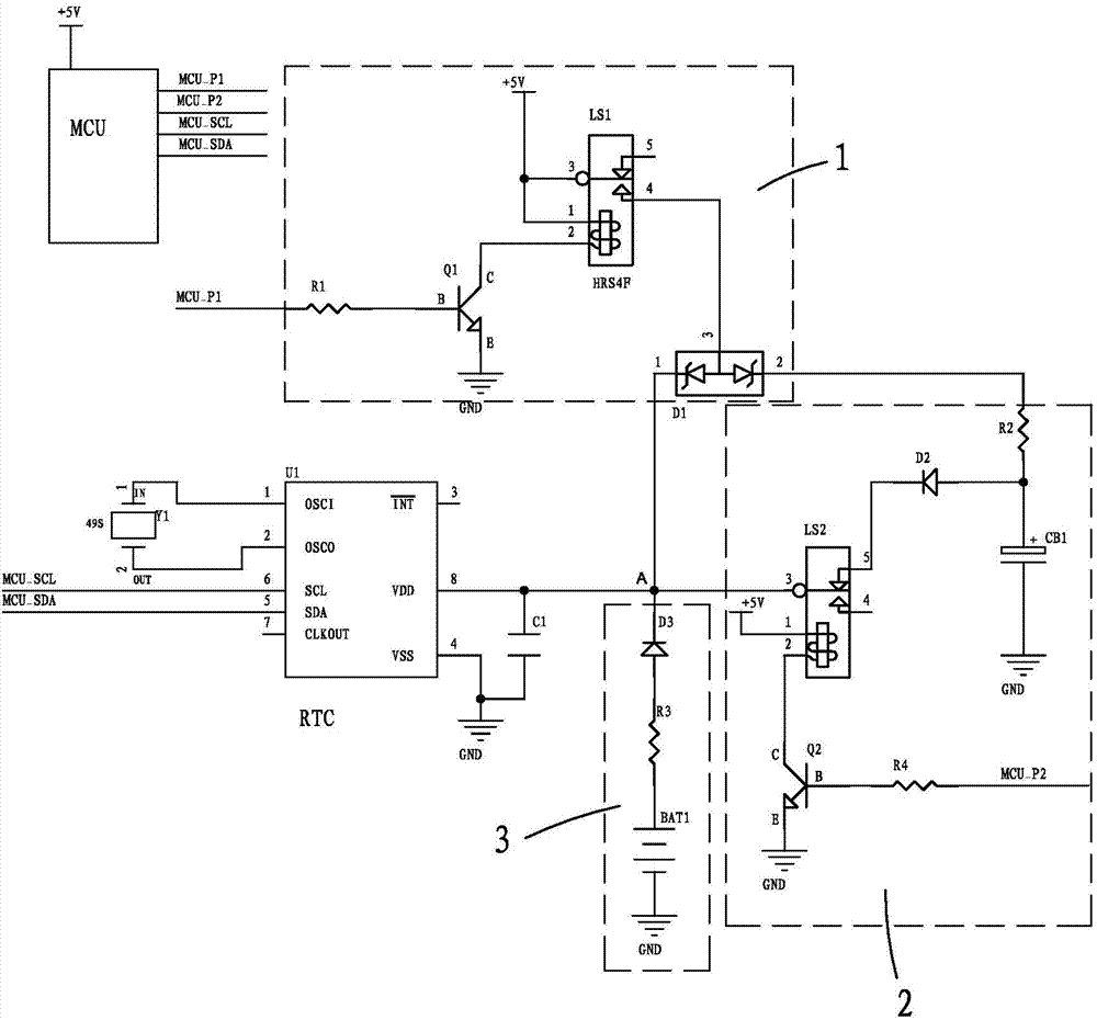
[0028] see figure 1 , a kind of RTC power management device, it is suitable for in the RTC system of equipment, and described power management device comprises an equipment power supply circuit 1, an RC charging and discharging circuit 2, a battery power supply circuit 3 and an MCU; Said equipment power supply The power supply circuit 1 is respectively connected to the battery power supply circuit 3 and the RC charging and discharging circuit 2, and the RC charging and discharging circuit 2 is also connected to the connection line between the equipment power supply circuit 1 and the battery power supply circuit 3 and formed on the connection line for The connection point A connected to the power supply end of the RTC chip U1, the device power supply circuit 1, the battery power supply circuit 3 and the RTC chip U1 are all controlled by the MCU, and the RTC chip U1 is the main chip of the RTC system. Button batteries are generally used in the battery power supply circuit 3 .

...

Embodiment 2

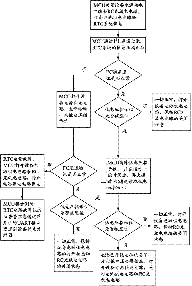
[0044] see figure 1 , a kind of RTC power management method, this management method is realized based on a kind of RTC power management device, and described power management device is applicable to the RTC system of equipment, and described RTC power management device comprises a device power supply circuit 1, A battery power supply circuit 3, an RC charging and discharging circuit 2, and an MCU; the power management method includes a shutdown power management step and a startup power management step;

[0045] The shutdown power supply management step is: when the device is shut down, if the voltage output by the RC charging and discharging circuit 2 is higher than the voltage output by the battery power supply circuit, the RC charging and discharging circuit 2 supplies power to the RTC system, if the RC The voltage output by the charging and discharging circuit 2 is equal to the voltage output by the battery power supply circuit 3, then the RC charging and discharging circui...


PUM


Abstract

The invention provides an RTC (real time clock) power management device which is applicable to an RTC system of equipment and comprises an equipment power supply circuit, a battery power supply circuit, an RC charging and discharging circuit and an MCU (micro-control unit). The equipment power supply circuit is respectively connected with the battery power supply circuit and the RC charging and discharging circuit, the RC charging and discharging circuit is connected onto a connecting wire for the equipment power supply circuit and the battery power supply circuit, a connecting point A connected with an RTC chip U1 power supply end is formed on the connecting wire, and the equipment power supply circuit, the battery power supply circuit and an RTC chip are controlled by the MCU. The invention further provides an RTC power management method. The device and the method have the advantages that time of the RTC system is reset by the aid of management for a backup power supply of the RTC system and a multichannel backup power supply scheme, and the problem of RTC low voltage mistaken alarm can be automatically checked.

Description

【Technical field】 [0001] The invention relates to an RTC power management method and device. 【Background technique】 [0002] At present, the RTC system in the media player usually uses a disposable button battery or a farad capacitor as a backup power supply. Disadvantage 1: When the disposable button battery is used, after the device is turned off (such as shutting down for a week), if the button battery is insufficient, the RTC system time will be reset; Disadvantage 2: When using a farad capacitor, the media player will During the online period (for example, at least one month), the self-discharge of the Farad capacitor will also cause insufficient power of the backup power supply, causing the RTC system time to be reset; Disadvantage 3: When the RTC clock chip in the RTC system is due to battery and Farad capacitor power When the battery is low or the circuit is disturbed by other disturbances to trigger a low battery warning, the RTC system cannot automatically trouble...

Claims


Application Information

Patent Timeline
IPC IPC(8): H02J9/04
Inventor 杨志荣董行群张子凤周捍章王勇
Owner FUJIAN STAR NET EVIDEO INFORMATION SYST CO LTD
Why Eureka
Try Eureka