

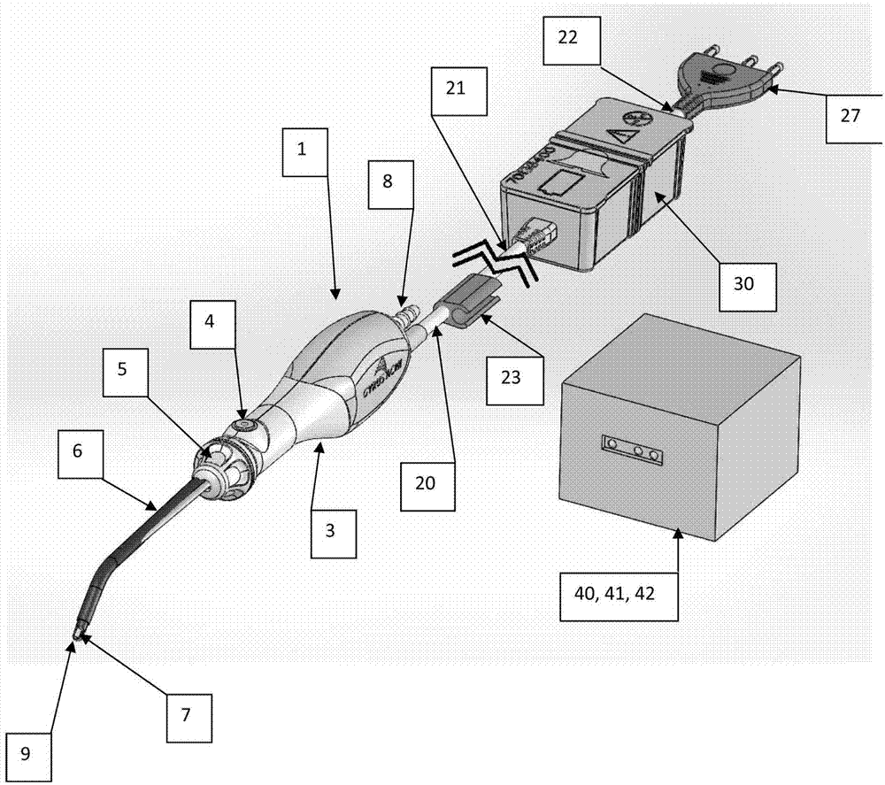
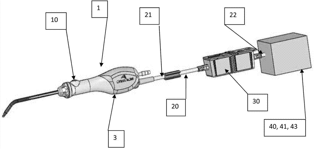
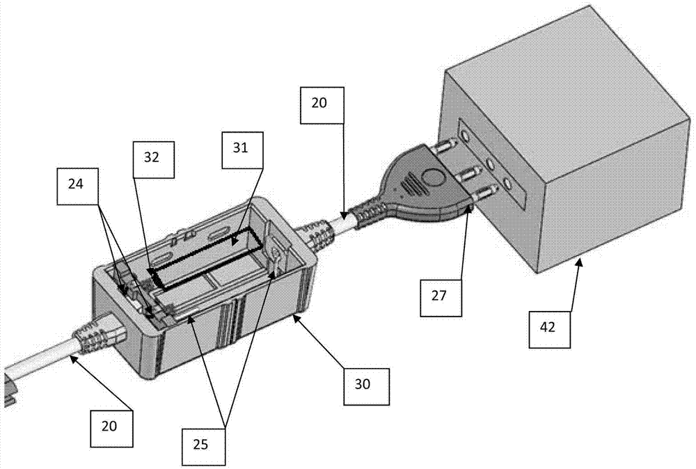
Battery pack attached to a cable
A battery pack and cable technology, applied to battery pack parts, batteries, circuits, etc., can solve the problems of bulky, endangering the sterility of patients, etc., achieve the effect of comfortable manipulation and operation, prevent damage, and reduce weight
- Summary
- Abstract
- Description
- Claims
- Application Information
AI Technical Summary
Problems solved by technology
Method used
Image

Examples
Embodiment Construction
[0015] The descriptions and illustrations presented herein are intended to acquaint those skilled in the art with respect to its teachings, its principles and its practical application. Those skilled in the art can adapt and apply this teaching in its many forms as best suited to the requirements of a particular use. Accordingly, the specific embodiments of the present teachings as set forth are not intended to be exhaustive or limiting of the teachings. The scope of the teaching, therefore, should be determined not with reference to the above description, but should be determined with reference to the appended claims, along with the full scope of equivalents to which such claims are entitled. The disclosures of all articles and references, including patent applications and publications, are incorporated by reference for all purposes. Other combinations are also possible, as will be gleaned from the following claims, which are also hereby incorporated by reference into this w...
PUM
 Abstract
Description
Claims
Application Information