
Expansion/shrinkage mechanism for steel plate winding shaft

A technology of expansion and contraction mechanism and steel plate coil, which is applied in the field of expansion and contraction mechanism, which can solve the problems of steel coil inner diameter deformation damage, indentation, inflexible taper blocks and grooves, etc., so as to improve the yield rate and reduce production waste Effect

Inactive Publication Date: 2015-02-11
KUNSHAN GUOZHI PRECISION MACHINERY
View PDF4 Cites 2 Cited by
  • Summary
  • Abstract
  • Description
  • Claims
  • Application Information

AI Technical Summary

Problems solved by technology

This structure has the following disadvantages in practice: the friction coefficient between the raised taper block of the main shaft and the corresponding groove on the blade is relatively large. If the tension of the coiled steel plate is too large, the blade will deform and cause expansion and contraction. Inflexibility or the taper block and the groove are stuck, so that the four blades cannot be completely closed when they are closed, and there will be gaps between the blades, which will leave indentations on the steel strip when the steel strip is coiled. Cause serious deformation and damage to the inner diameter of the steel coil, resulting in production waste

Method used


Image

  • Expansion/shrinkage mechanism for steel plate winding shaft
  • Expansion/shrinkage mechanism for steel plate winding shaft
  • Expansion/shrinkage mechanism for steel plate winding shaft

Examples


Embodiment 1

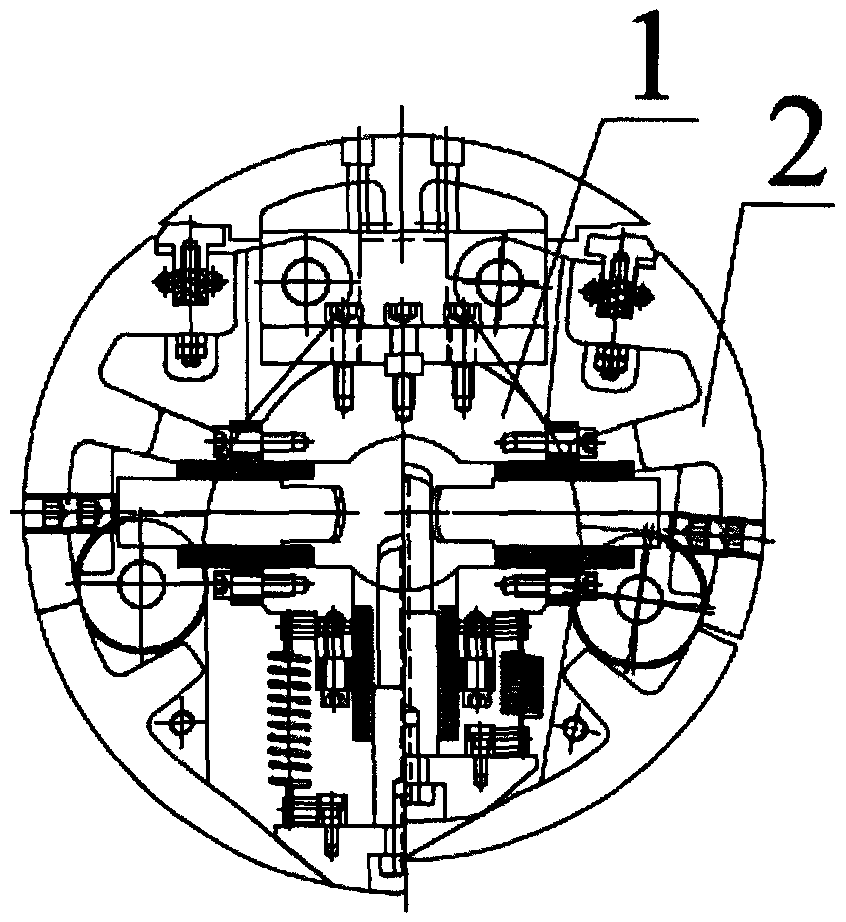
[0019] see Figure 1 to Figure 5 , Embodiment 1 of the present invention: an expansion and contraction mechanism for a steel plate coiling shaft, the steel plate coiling shaft is a long cylindrical structure composed of four blades 2, and the expansion and contraction mechanism includes an expansion and contraction main shaft 1 and a plurality of expansion and contraction oblique tips 20, the expansion and contraction main shaft 1 is arranged at the central position of the cylindrical mechanism, and a plurality of expansion and contraction oblique tips 20 are arranged on four blades 2 in equal quantity; on the expansion and contraction main shaft 1 A groove 10 is provided at a position corresponding to each expansion-contraction oblique tip bar 20 , and each expansion-contraction oblique tip bar 20 can be inserted into the corresponding groove 10 on the expansion-contraction main shaft 1 .

[0020] In this embodiment, the bottom of the groove 10 is a slope, and the bottom of t...

Embodiment 2

[0025] Embodiment 2: The difference between this embodiment and Embodiment 1 is that the length of the slope at the bottom of the groove 10 of the expansion-contraction spindle 1 is 120 mm. The length of the surface of the protruding blade 2 of the expanding and shrinking oblique tip bar 20 is 200 mm.

Embodiment 3

[0026] Embodiment 3: The difference between this embodiment and Embodiment 1 is that the length of the slope at the bottom of the groove 10 of the expansion-contraction spindle 1 is 120 mm. The length of the surface of the protruding blade 2 of the expanding and shrinking oblique tip bar 20 is 150mm.


PUM

PropertyMeasurementUnit
Lengthaaaaaaaaaa
Lengthaaaaaaaaaa
Lengthaaaaaaaaaa

Abstract

The invention discloses an expansion / shrinkage mechanism for a steel plate winding shaft. The steel plate winding shaft is a long cylindrical structure consisting of four blades; the expansion / shrinkage mechanism comprises an expansion / shrinkage main shaft and a plurality of expansion / shrinkage inclined strips; the expansion / shrinkage main shaft is arranged in the center position of the cylindrical structure; the plurality of expansion / shrinkage inclined strips are equally arranged on the four blades; the expansion / shrinkage main shaft is provided with grooves corresponding to all the expansion / shrinkage inclined strips; and each of the expansion / shrinkage inclined strips can be embedded in the corresponding grooves of the expansion / shrinkage main shaft. Through the mode, the expansion / shrinkage mechanism for the steel plate winding shaft can realize seamless closing for the blades of the steel plate winding shaft so as to leave no dents on steel strips in the winding of the steel strips.

Description

technical field [0001] The invention relates to the field of strip steel coilers, in particular to an expansion and contraction mechanism capable of realizing seamless expansion and contraction of a steel plate coiling shaft. Background technique [0002] The coiler is the equipment for collecting and sorting the strip steel products. The quality of its coiling has a direct impact on the final product of the strip steel. As the core component of the coiler, the reel is directly related to the product to be rolled. The reel of the existing coiler is generally composed of four closed blades, and the four closed blades form a cylindrical structure reel. There is a main shaft in the center of the reel, and a plurality of raised taper blocks are arranged on the main shaft. Correspondingly, each blade is provided with a groove that matches the raised taper block, and the reel can be uncoiled or unrolled by matching the raised taper block on the spindle with the groove on each bla...

Claims


Application Information

Patent Timeline
IPC IPC(8): B21C47/30
Inventor 李聪兴
Owner KUNSHAN GUOZHI PRECISION MACHINERY
Learn More