

Hub casting system
A pouring system and hub technology, applied in casting molding equipment, molds, cores, etc., can solve problems such as shrinkage holes/loose defects, and achieve the effect of ensuring integrity, overcoming pouring defects, and eliminating pouring defects
Active Publication Date: 2015-02-11
SHIYAN KAIQI CASTING
View PDF6 Cites 0 Cited by
- Summary
- Abstract
- Description
- Claims
- Application Information
AI Technical Summary
Problems solved by technology
[0007] For the above three traditional solutions, although no defects can be seen from the surface, the shrinkage cavity / loose defects are obvious after the cut surface
Method used
View moreImage
Smart ImageViewing Examples

Examples
Embodiment Construction
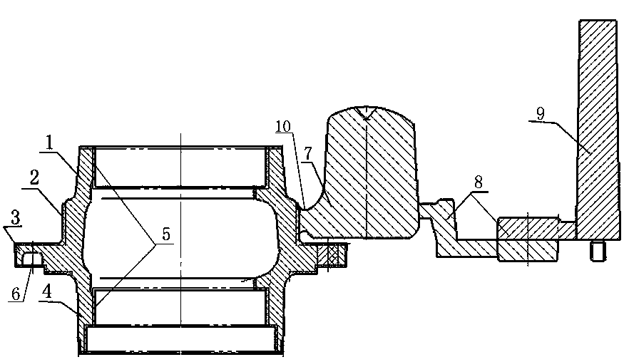
[0019] The present invention as figure 2 shown.
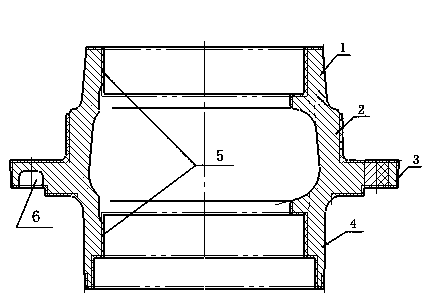
[0020] A pouring system for a wheel hub. The outer structure of the wheel hub is divided into a first step 1, a second step 2, a flange 3 and a straight cylinder 4 in sequence, and the interior is provided with a bearing installation position 5, and the flange 3 is provided with a mounting groove. 6. A feeding riser 7 is provided on the outer circle of the second step 2, and the feeding riser 7 is connected to the sprue 9 through the runner 8.
[0021] There is a distance between the 7 roots of the feeding riser and the 3 flanges, and the distance is 3-5 mm.
[0022] Fractures 10 are also provided on the root of the feeding riser 7 and the second step 2 .
Login to View More PUM
 Abstract
The invention provides a hub casting system. The exterior of a hub is structurally divided into a first step, a second step, a flange and a straight barrel in sequence, and a bearing mounting position is arranged in the hub in a penetration way, wherein a mounting groove is formed in the flange; a feeding head is arranged on the outer circle of the second step, and is connected with a straight runner through a transverse runner; a gap is formed between the root of the feeding head and the root of the flange, and is 3 to 5mm; a fracture is formed in the root of the feeding head and the second step. According to the hub casting system, the casting position of a casting is shifted to a position to be fed, that is, the feeding head is shifted to the second step on the flange, the feeding head is directly used for feeding to the second step, the straight runner and the transverse runner are continuous, and the casting is cast by virtue of the feeding head, so that the defect of shrinkage is substantially eliminated, and a result meets the requirement of a product.
Description
technical field [0001] The invention relates to a casting structure of auto parts, in particular to a pouring system of a wheel hub. Background technique [0002] The outer structure of the wheel hub in the auto parts is divided into a first step 1, a second step 2, a flange 3 and a straight cylinder 4 in sequence, and a bearing installation position 5 is provided through the interior, and a mounting groove 6 is provided on the flange. Such as figure 1 shown. [0003] At present, under the traditional method, the gating system design of the hub generally adopts the following scheme: [0004] Solution 1: In order to have a relative feeding of the second step 2 and the straight cylinder 4 on both sides of the flange 3, especially the shrinkage cavity / looseness will occur at the root of the flange 3 and the step 2, so the casting method of the hub will be adopted There is a thermal feeding riser at the outer circle of Lan 3, so that the molten iron can pass through to realiz...
Claims
Login to View More Application Information
Patent Timeline
 Patent Type & AuthorityApplications(China)
IPC IPC(8): B22C9/08B22C9/28
CPCB22C9/082B22C9/28
Inventor赵久明王鑫刘强唐琳李海滨曹本宏汪鹏董焱
OwnerSHIYAN KAIQI CASTING