Novel follow-up small chilling block application process for automobile engine crankshaft

An automotive engine and follow-up technology, which is applied in the field of auto parts, can solve problems such as large contact surface, affecting processing efficiency, and manual cleaning, and achieve the effects of improving quality, strengthening cooling effect, and eliminating shrinkage defects

Active Publication Date: 2021-11-12
上海圣德曼铸造海安有限公司
View PDF7 Cites 0 Cited by
  • Summary
  • Abstract
  • Description
  • Claims
  • Application Information

AI Technical Summary

Problems solved by technology

[0003] In order to meet the position quality requirements of crankshaft connecting rods, similar products currently cast by traditional technology are adopted: P1 connecting rods are placed with the external chilled iron process, the single weight of the chilled iron is 0.35kg, and the entire chilled iron is connected with the P1 connecting rod of the crankshaft. The contact surface with the P1 connecting rod reaches 5500mm2. Due to the large contact surface with the P1 connecting rod, the follow-up cleaning workload of the cold iron is extremely large, and it cannot be cleaned manually. A special press is required for cleaning, which increases the workload of cleaning
Due to the large contact surface between the outer chill iron and the connecting rod, the surface coating of the outer chill iron must be applied in place, otherwise the abnormal coating will cause the outer chill iron to be pressed down even with a press, and the contact surface is too large, resulting in processing failure. The hardness of the contact surface corresponding to the cold iron is higher than that of other positions, which affects the processing efficiency

Method used


Image

  • Novel follow-up small chilling block application process for automobile engine crankshaft
  • Novel follow-up small chilling block application process for automobile engine crankshaft
  • Novel follow-up small chilling block application process for automobile engine crankshaft

Examples


Embodiment Construction

[0019] The following will clearly and completely describe the technical solutions in the embodiments of the present invention with reference to the accompanying drawings in the embodiments of the present invention. Obviously, the described embodiments are only some, not all, embodiments of the present invention.

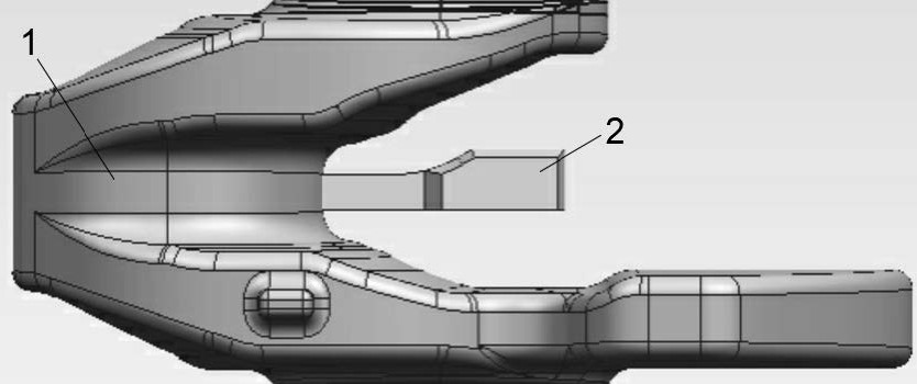
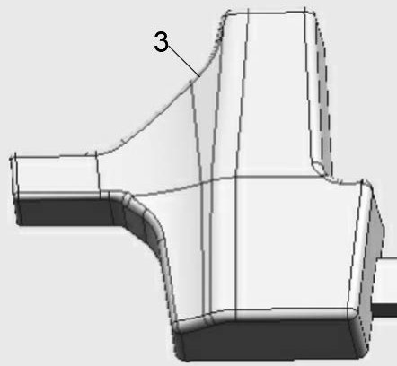
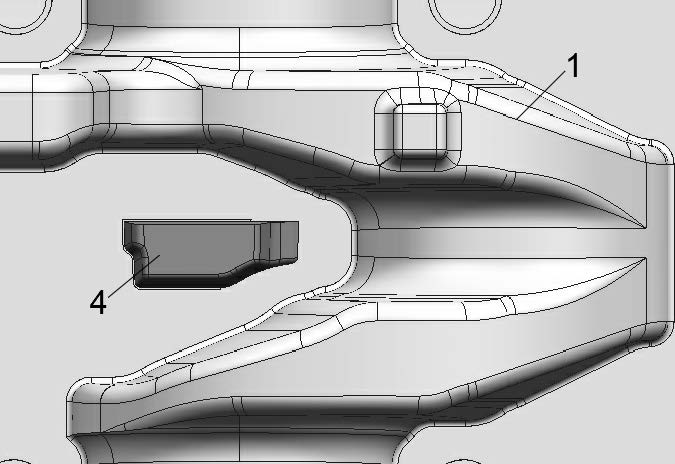
[0020] refer to Figure 1-4 , a new type of small cold iron application process for automobile engine crankshafts, including crankshaft P1 connecting rod 1, small cold iron 2, small cold iron production mold 3, small cold iron in the P1 connecting rod lower die mold Structure 4 and the mold structure 5 on the upper mold of the P1 connecting rod with the small chill iron. A small chill iron 2 is provided on the crankshaft P1 connecting rod 1. According to the type requirements of the crankshaft P1 connecting rod 1, the The crankshaft mold is divided into upper and lower parts. The small chill iron located in the lower mold of the crankshaft is in the mold structure 4 ...


PUM


Abstract

The invention discloses a novel follow-up small chilling block application process for an automobile engine crankshaft. A crankshaft P1 connecting rod, a follow-up small chilling block, a follow-up small chilling block manufacturing mold, a mold structure of the follow-up small chilling block on a P1 connecting rod lower mold and a mold structure of the follow-up small chilling block on a P1 connecting rod upper mold. The application process has the beneficial effects that the crankshaft casting modulus is 8.5 mm, the casting modulus of the corresponding P1 connecting rod position is 10.3 mm, and the inner side of the machined crankshaft P1 connecting rod has the micro shrinkage porosity defect; the shrinkage porosity defect of a machining shrinkage cavity of the crankshaft P1 connecting rod position is perfectly overcome through the use of the follow-up small chilling block; the follow-up small chilling block is arranged corresponding to the crankshaft P1 connecting rod position in the technological structure, the piece weight of the follow-up small chilling block is 0.04 Kg, according to the parting requirement of the crankshaft P1 connecting rod, a crankshaft mold is divided into an upper part and a lower part, namely a mold structure positioning part located on the crankshaft lower mold and a mold structure direct contact part with the P1 connecting rod at the crankshaft upper mold.

Description

technical field [0001] The invention relates to a technology for applying a small chill iron with a shape, in particular to a technology for applying a new type small chill iron for an automobile engine crankshaft, and belongs to the technical field of auto parts. Background technique [0002] The crankshaft of the automobile engine is a large platform product, which can be applied in various automobile models. The client requires that the position of the connecting rod of the crankshaft product is not allowed to have microscopic shrinkage defects after magnetic particle inspection, that is, after visual inspection There must be no defects, and the magnetic particle inspection after processing must not have defects. The appearance and internal quality requirements are very high. Such high quality requirements for customers make the production enterprises face severe technical challenges. [0003] In order to meet the quality requirements of the position of the crankshaft con...

Claims


Application Information

Patent Timeline
Patent Type & Authority Applications(China)
IPC IPC(8): B22D15/04
CPCB22D15/04
Inventor 周小龙张晓锋龚华林刘金林
Owner 上海圣德曼铸造海安有限公司
Why Eureka
Try Eureka