Manual gear type column switch hoisting device and application thereof

A lifting device and pole-mounted switch technology, which is applied in the direction of switchgear, hoisting device, electrical components, etc., can solve the problems that the lifting vehicle cannot be on call, the workplace occupies a large area, and the lifting vehicle cannot enter, etc. , to achieve long service life, reduce operating personnel, good economic benefits and market prospects

Inactive Publication Date: 2015-02-11
国网山东省电力公司聊城供电公司
View PDF13 Cites 1 Cited by
  • Summary
  • Abstract
  • Description
  • Claims
  • Application Information

AI Technical Summary

Problems solved by technology

However, the device is inconvenient to use, and a bracket needs to be erected when the isolating switch is installed, the preliminary work is complicated, and it is not convenient to carry
[0006] To sum up, there are several problems with the existing lifting methods. First, lifting requires a large number of operators. The average required number of workers is at least 5, and the average lifting time is at least 24 minutes. There are many hidden dangers; the second is that the workplace occupies a large area, especially in the fields of young crops and vegetables, and the social compensation costs are higher; the third is that some workplaces are narrow or have inconvenient traffic, and lifting vehicles cannot enter, and rural lifting vehicles cannot be called on call to, low work efficiency

Method used


Image

  • Manual gear type column switch hoisting device and application thereof
  • Manual gear type column switch hoisting device and application thereof
  • Manual gear type column switch hoisting device and application thereof

Examples


Embodiment 1

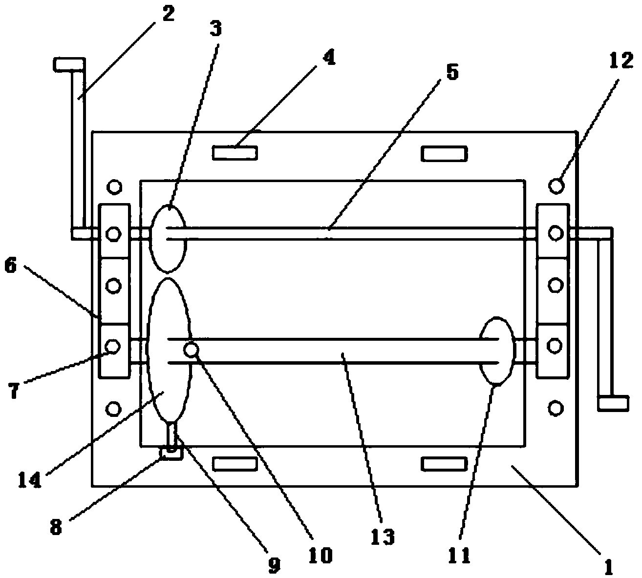
[0042] A lifting device for a switch on a manual gear type column, the lifting device includes a main body, a transmission device and a fixing device,

[0043] Wherein, the main body includes a three-dimensional frame 1 which is welded vertically by four angle steels, and the angle steel sizes used are ∠80×8, 54 cm and ∠80×8, 32 cm; fixed supports 6 are symmetrically arranged on the angle steels on both sides of the three-dimensional frame 1, The fixed bracket 6 is installed on the angle steel on both sides through the fixed bracket mounting holes 12 at the upper and lower ends;

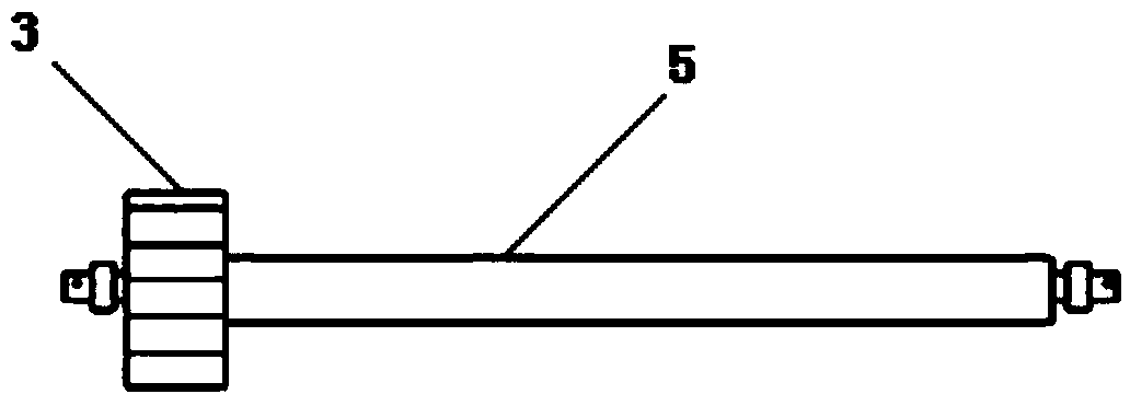
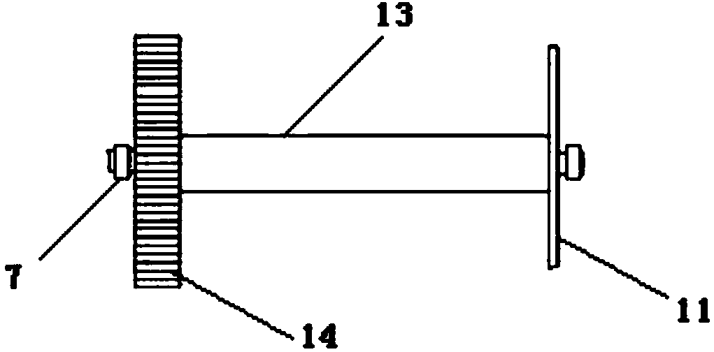
[0044]The transmission device includes a first transmission shaft 5 and a second transmission shaft 13, the first transmission shaft 5 is also called a moving shaft, the second transmission shaft 13 is also called a winch shaft, the first transmission shaft 5 and the second transmission shaft 13 The gears are respectively welded on the top, wherein the gear on the first transmission shaft 5 is the dr...

Embodiment 2

[0049] A lifting device for a switch on a manual gear type column, the structure is as described in Embodiment 1, the only difference is that the lifting device also includes an automatic pawl mechanism, the automatic pawl mechanism includes a fixed piece 8 and a brake piece 9, the fixed The sheet 8 is arranged on the three-dimensional frame and is located below the driven wheel, the brake sheet 9 is connected to the fixed sheet 8 in rotation, and the end of the brake sheet 9 is set on the driven wheel 14 . During the lifting operation, it is sometimes necessary to suspend the operation during the lifting process, and the automatic pawl mechanism can function as a pause switch to prevent the gear from reversing. At the same time, due to the heavy weight of the switch, in order to avoid the accidental fall of the switch, the automatic pawl mechanism can effectively block the reverse rotation of the gear and prevent accidents.

Embodiment 3

[0051] The method for using the manual gear type lifting device to lift the switch on the column includes the following steps,

[0052] (1) According to the diameter of the pole of the distribution line at the place where the switch is installed, select a suitable U-shaped hoop, pass the two ends of the U-shaped hoop through the guide rail slide groove 4 on the three-dimensional frame 1, and then tighten the lifting device to fix it on the on the pole;

[0053] (2) Put the two rocking handles 2 into the two ends of the first transmission shaft 5 respectively, so that the screw holes on the rocking handle 2 correspond to the screw holes on the first transmission shaft 5, and insert bolt pins into the screw holes , and tighten the bolt pin to fix the rocking handle 2 and the first drive shaft 5 together;

[0054] (3) One end of the wire rope is fixed in the rope hole 10 on the second transmission shaft 13 with bayonet pins, and the winding direction of the wire rope is determin...


PUM


Abstract

The invention relates to a manual gear type column switch hoisting device and application of the manual gear type column switch hoisting device. The hoisting device comprises a main body, a transmission device and a fixing device, wherein the transmission device comprises a first transmission shaft and a second transmission shaft; gears which are meshed with each other for transmission are respectively arranged on the first transmission shaft and the second transmission shaft; the two ends of the first transmission shaft and the second transmission shaft are arranged on a three-dimensional framework; the two ends of the first transmission shaft are respectively fixedly connected with a shaking handle; a steel wire rope is arranged on the second transmission shaft. When the hoisting device is used, the main body is fixed on an electric pole by utilizing a hoop, the steel wire rope penetrates through fixed pulleys on a cross arm at the top of the electric pole and is used for tying switch equipment, and then a worker shakes the handle to hoist the switch equipment. Compared with the traditional hoisting mode, the hoisting device has the advantages that the operators are reduced, the operation time is shortened, the working efficiency is improved, and the operation cost is reduced.

Description

technical field [0001] The invention relates to a lifting device for a switch on a manual gear type pole and an application thereof, which belongs to the technical field of electric equipment. Background technique [0002] In the process of distribution network construction, in order to realize distribution network automation, it is necessary to install section and boundary switches to cooperate with the main station to complete the automatic isolation of faults. The weight of the switch itself is about 210 kg, and its mass is large, so it is inconvenient to install. At present, there are several common lifting methods for switches on the column. One is to install the fixed pulley on the cross arm, and use manpower to pull the rope to achieve the purpose of lifting the switch; the other is to combine the moving and fixed pulleys, and lift the switch by manpower; The third is to use a crane to hoist the switch to achieve the purpose of hoisting. [0003] Chinese patent docum...

Claims


Application Information

Patent Timeline
Patent Type & Authority Applications(China)
IPC IPC(8): B66D1/04B66D1/18B66D1/60H02B3/00
CPCB66D1/04B66D1/18B66D1/60H02B3/00
Inventor 杨延辉李冬冬王继坤郭婷婷陈中一王书典
Owner 国网山东省电力公司聊城供电公司
Why Eureka
Try Eureka