General machine engine cooling structure

An engine cooling and general machine technology, applied in the direction of engine cooling, machine/engine, engine components, etc., can solve the problem that the forced air cooling structure is not interchangeable, so as to meet the requirements of forced air cooling heat dissipation, reduce heat load, Improve the effect of the cooling effect

Inactive Publication Date: 2015-02-11
CHONGQING DINKING POWER MACHINERY
View PDF6 Cites 3 Cited by
  • Summary
  • Abstract
  • Description
  • Claims
  • Application Information

AI Technical Summary

Problems solved by technology

Ordinary vehicle engines and general-purpose engines are not only different in internal structure,

Method used


Image

  • General machine engine cooling structure
  • General machine engine cooling structure
  • General machine engine cooling structure

Examples


Embodiment Construction

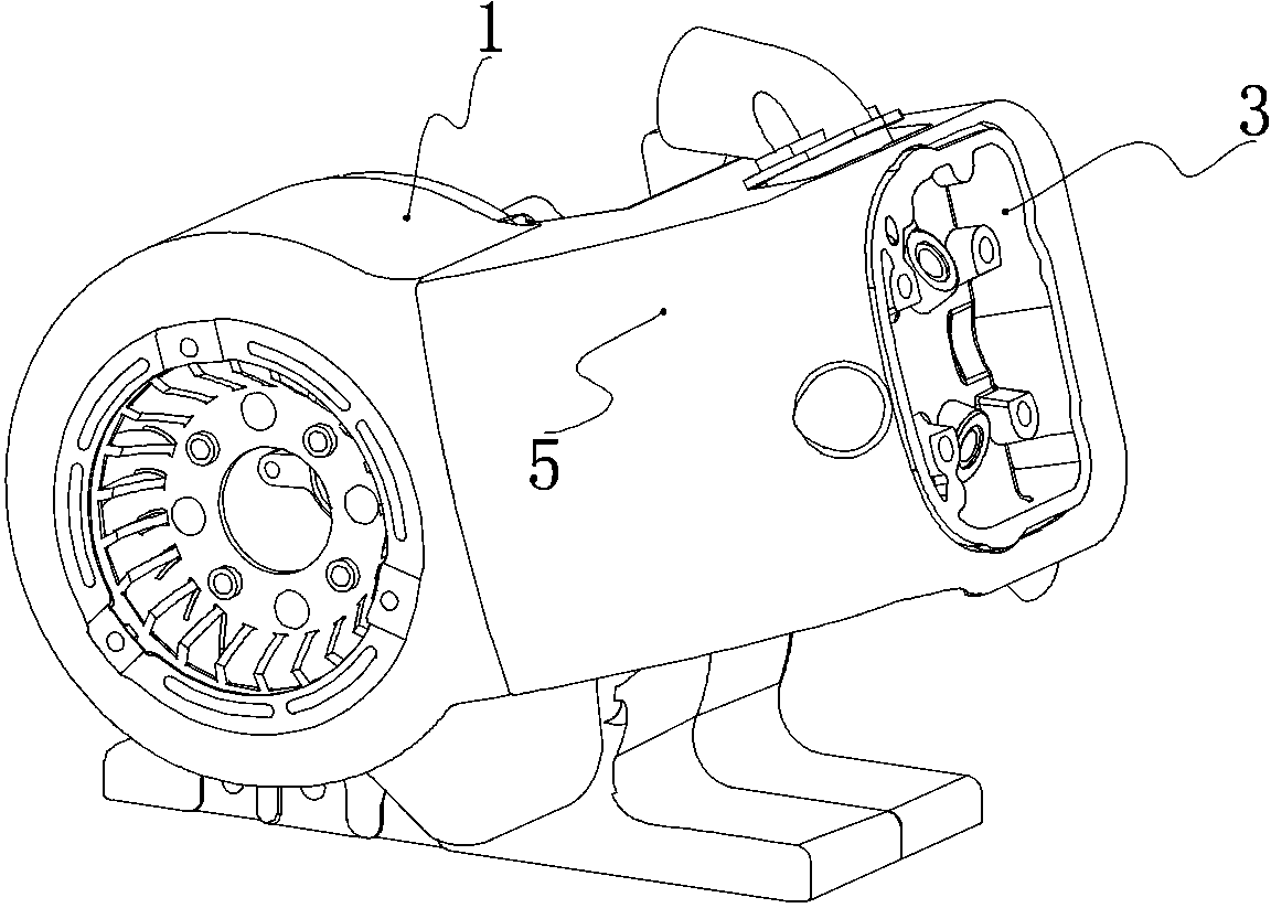
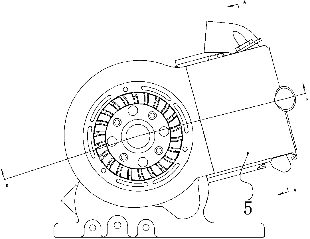
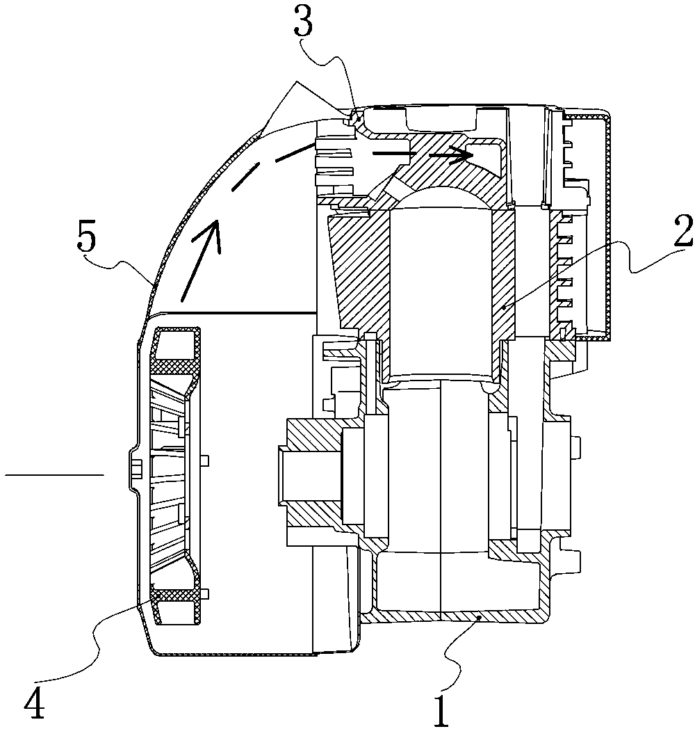
[0016] Such as figure 1 , figure 2 and image 3 As shown, in the general machine engine of the present invention, the crankcase 1 is located at the bottom of the whole engine, and the top of the crankcase 1 is provided with a cylinder block 2 and a cylinder head 3 in sequence. The magneto is located in the crankcase 1, the axle sleeve on the rotor of the magneto protrudes from the crankcase 1, and the cooling fan 4 is installed on the axle sleeve through the fan holder. The air guide cover 5 covers the cooling fan 4, the cylinder body 2 and the cylinder head 3, and the cooling air flow channel blowing from the cooling fan 4 to the cylinder head 3 is formed in the air guide cover 5, and the cooling air flow channel is at the cylinder head 3. Distributed to form three cooling air ducts. Such as Figure 4 As shown, the three cooling air passages in the figure are indicated by A, B, and C respectively, and the flow direction of the cooling air in the figure is indicated by ar...


PUM


Abstract

The invention relates to a general machine engine cooling structure, which comprises a crank shaft box body, a cylinder body, a cylinder head and a magnetic motor, wherein the magnetic motor is positioned in the crank shaft box body, a shaft sleeve arranged on a magnetic motor rotor extends out of the crank shaft box body, a cooling fan is arranged on the shaft sleeve through a fan retainer, the cooling fan, the cylinder body and the cylinder head are covered in an air guide cover, a flow passage blowing to the air cylinder is formed in the air guide cover, three cooing air passages are formed in the cylinder head, the air guide cover gathers cooling air blown out from the fan into the flow passages, the air is blown into the three cooling air passages of the cylinder head through the flow passage, meanwhile, the forced air cooling is carried out on the outside and the inside of the cylinder head, and the cooling effect is greatly improved. The heat load of the engine can be effectively reduced, so that the engine can realize the normal heat radiation at a high rotating speed. The general machine engine cooling structure has the advantages that the structure is simple, the cost is low, the maintenance is convenient, and the forced air cooling heat radiation requirements of a high-speed general machine engine are met.

Description

technical field [0001] The invention relates to a general engine, in particular to a cooling structure of the general engine. Background technique [0002] Engines are generally divided into water-cooled and air-cooled. Although the cooling effect of water-cooled engines is good, the cost of water-cooled engines is high and frequent maintenance is required. Although the cost of natural air-cooled engines is low, the cooling effect is not very satisfactory, which often leads to a high heat load on the engine. Especially for high-speed general-purpose engines, due to their own working characteristics, the engine works under high-speed conditions, and this working method causes the engine heat load to be much higher than that of ordinary generator sets. At present, most manufacturers do not have a good method to solve the above heat load problem. Because it is used in generator sets, considering cost, maintenance and safety issues, water cooling is not an ideal solution. Ord...

Claims


Application Information

Patent Timeline
IPC IPC(8): F01P1/02F01P5/06F02F1/28
Inventor 莫启雄罗雄彬张学义
Owner CHONGQING DINKING POWER MACHINERY
Why Eureka
Try Eureka