Pump Arrangement

A technology in which equipment and pumps are connected in series. It is applied to mechanical equipment, pumps, and pump control. It can solve problems such as high power and slow construction, and achieve the effect of simple construction and mechanical construction.

Inactive Publication Date: 2015-02-11
HELLA KG HUECK & CO
View PDF6 Cites 2 Cited by
  • Summary
  • Abstract
  • Description
  • Claims
  • Application Information

AI Technical Summary

Problems solved by technology

Vacuum pumps or series-connected vacuum pumps are known for this purpose; these known devices have the disadvantage that the required pressure or vacuum builds up only relatively slowly and / or requires relatively high power

Method used


Image

  • Pump Arrangement
  • Pump Arrangement
  • Pump Arrangement

Examples


example 1

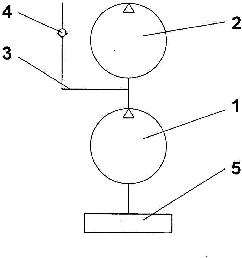
[0023] as by figure 1 As can be seen, the first pump arrangement of the first embodiment comprises a first pump 1 , a second pump 2 and a bypass 3 with a first bypass valve 4 . The pumps 1 , 2 are designed as vacuum pumps and are equipped with an electric motor for the drive, the first pump 1 having a significantly greater delivery capacity than the second pump 2 .

[0024] The first pump 1 is connected on the suction side to a container 5 to be evacuated, for example a brake booster, in which a predetermined pressure range (negative pressure) is to be maintained during operation. The second pump 2 is connected in series with the first pump 1 , which means that it is connected on the suction side to the pressure side of the first pump 1 . Parallel to the second pump 2 , a bypass 3 is connected to the connecting line between the pumps 1 , 2 , in which bypass a first bypass valve 4 is arranged. The first bypass valve 4 forms, for example, a check valve 4 .

[0025] A pump sys...

example 2

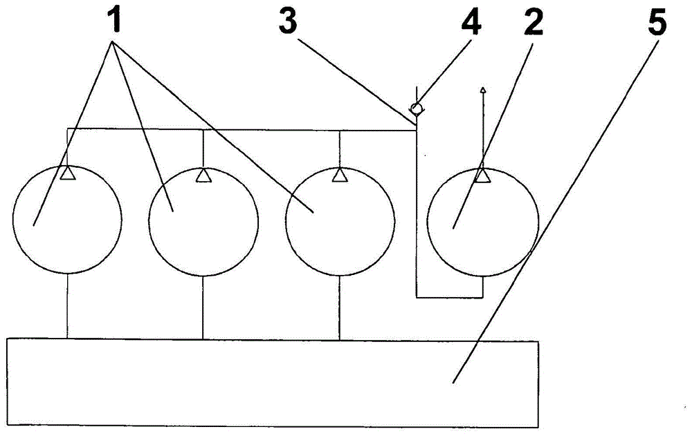
[0030] The second embodiment is in figure 2 shown in and differ from the first embodiment by the following content:

[0031] Several, here three, first pumps 1 are connected in parallel. A bypass 3 with a bypass valve 4 is connected upstream of the second pump 2 to the common pressure line of the first pump 1 .

[0032] The pumps 1 , 2 and in particular the first pump 1 are preferably identical.

example 3

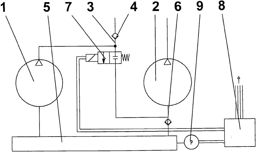
[0034] The third embodiment is image 3 shown in and differ from the first embodiment by the following content:

[0035] The suction side of the second pump 2 is additionally connected to the container 5 , wherein a second bypass valve 6 is installed in the associated suction line. This bypass valve is preferably constructed identically to the first bypass valve and is arranged in such a way that the second bypass valve does not interfere with the connection of the suction side to the first pump 1 and that when the pressure in the suction line is greater than that in the container 5, the second bypass valve is automatically closed.

[0036] Furthermore, a valve 7 , for example a solenoid valve, is arranged in the connecting line between the pumps 1 , 2 , which causes an opening / closing function. The valve 7 can here be actuated electrically by the control device 8 , for example as a function of the pressure in the container 5 . A pressure sensor 9 is arranged on the contain...


PUM


Abstract

A pump arrangement comprising at least one first pump and at least one second pump that can be connected or is connected in series behind the first pump. The pump arrangement has a simple construction, lowest possible pump capacity requirements, and quickly establishes a required pressure or vacuum pressure. This is achieved in that a pump capacity of the first pump or a sum of the pump capacities of the first pumps is much greater than a pump capacity of the second pump and that a bypass with a first overflow valve is connected between the first pump and the second pump.

Description

technical field [0001] The invention relates to a pump arrangement comprising at least one first pump and at least one second pump which is connected or can be connected in series downstream of the first pump. Background technique [0002] Such pump devices are known per se and are used to generate high pressures or rough vacuums up to extremely high vacuums. Pump devices are described, for example, on www.de.Wikipedia.org, keyword "vacuum pump", chapter "Generation of ultra-high vacuum". According to this, a backing vacuum is first generated with a mechanically acting vacuum pump and then an ultrahigh vacuum is generated with a turbomolecular pump. [0003] The terms "pump" and "vacuum pump" within the meaning of the present invention include not only the actual pump but also, if applicable, the pump chamber formed in the pump. Here, the term pump chamber is defined as one of several chambers inside the compression chamber. [0004] Vacuum pumps are used, for example, in...

Claims


Application Information

Patent Timeline
Patent Type & Authority Applications(China)
IPC IPC(8): F04D25/16
CPCF04D27/009F04D27/0215F04D19/04F04D25/16
Inventor T·许泽
Owner HELLA KG HUECK & CO
Why Eureka
Try Eureka