Clutch, vehicle and clutch driven plate with three-level torsion damping mechanism

A torsional vibration damping and clutch technology, applied in the clutch field, can solve the problems of wasting space, weak bearing capacity, unstable work, etc., and achieve the effect of increasing the bearing capacity, improving the bearing capacity, and improving the vibration reduction effect.

Inactive Publication Date: 2015-02-11
SAIC MOTOR
View PDF6 Cites 9 Cited by
  • Summary
  • Abstract
  • Description
  • Claims
  • Application Information

AI Technical Summary

Problems solved by technology

[0007] The object of the present invention is to provide a clutch driven plate with a three-stage torsional vibration damping mechanism, so as to solve the unstable operation of the clutch in the critical position between the pre-vibration damping level and the main damping level in the prior art problems, thereby improving the torsional vibration damping performance of the vehicle under certain small torque conditions, and making the torque characteristics of the input gearbox more stable
[0008] Another object of the present invention is to provide a clutch driven disc with a three-stage torsional vibration damping mechanism to solve the problems of wasted space and weak bearing capacity of the two-stage vibration damping bushing plate in the prior art, so that all stages The damping mechanism can be better installed and combined to form independent stiffness and damping to achieve better damping effect and improve the load capacity of the clutch

Method used


Image

  • Clutch, vehicle and clutch driven plate with three-level torsion damping mechanism
  • Clutch, vehicle and clutch driven plate with three-level torsion damping mechanism
  • Clutch, vehicle and clutch driven plate with three-level torsion damping mechanism

Examples


Embodiment Construction

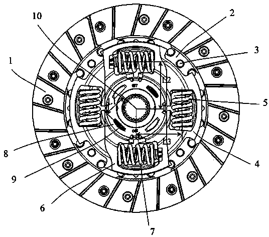
[0030] Specific embodiments of the present invention will be described in detail below in conjunction with the accompanying drawings.

[0031] It is easy to understand that, according to the technical solution of the present invention, those skilled in the art can propose multiple structural modes and implementation modes that can be replaced without changing the essence and spirit of the present invention. Therefore, the following specific embodiments and drawings are only exemplary descriptions of the technical solution of the present invention, and should not be regarded as the entirety of the present invention or as a limitation or restriction on the technical solution of the present invention.

[0032] The directional terms such as up, down, left, right, front, back, front, back, top, and bottom that appear or may appear in this specification are defined relative to the configuration shown in each drawing, and they are relative Therefore, it may change accordingly accordi...


PUM


Abstract

The invention discloses a clutch driven plate with a three-level torsion damping mechanism. The clutch driven plate comprises a friction sheet, a driven plate steel sheet, a primary damping shaft sleeve plate, a primary damping spring, a secondary damping shaft sleeve plate, a secondary damping spring, a pre-damping shaft sleeve plate and a pre-damping spring, the secondary damping spring is serially connected with the pre-damping spring and the primary damping spring, the pre-damping spring is provided with a first force arm, the secondary damping spring is provided with a second force arm, the primary damping spring is provided with a third force arm, the first force arm is smaller than the second force arm and the third force arm, and the third force arm is smaller than or equal to the second force arm. The internal space of the clutch driven plate is more reasonably used without increasing the size of the clutch driven plate, the bearing capacity of a clutch is improved, and damping effect is effectively improved.

Description

technical field [0001] The invention relates to a clutch, in particular to a clutch driven disc with a three-stage torsional damping mechanism, a clutch including the clutch driven disc and a vehicle. Background technique [0002] The structure of the traditional clutch driven disc with torsional vibration damping mechanism is as follows: figure 1 As shown, the friction plate 100 and the splined hub 106 are connected by damping springs (including the main damping spring 102 and the idle damping spring 103 ), which have tangential elasticity to eliminate high-frequency resonance and play a buffering role. Between the friction plate 100, the spline hub 106, and the damping plate 107, there is a vibration damping plate 104, which is elastically clamped by a disc spring 105 to play a role of frictional damping, and to keep the damping torque stable to absorb The engine outputs fluctuating energy and attenuates low-frequency vibrations. [0003] In the structure of the traditio...

Claims


Application Information

Patent Timeline
Patent Type & Authority Applications(China)
IPC IPC(8): F16D13/60F16F15/123
Inventor 方伟荣徐旭初陶林杰赵朝阳朱新星张伯平
Owner SAIC MOTOR
Why Eureka
Try Eureka