Pulse timing and counting device and method for liquid flow verification

A technology of pulse timing counting and liquid flow, applied in liquid/fluid solid measurement, measurement device, frequency measurement device, etc., can solve problems such as difficulty in ensuring synchronization

Active Publication Date: 2015-02-11
BEIJING AEROSPACE INST FOR METROLOGY & MEASUREMENT TECH +1
View PDF5 Cites 11 Cited by
  • Summary
  • Abstract
  • Description
  • Claims
  • Application Information

AI Technical Summary

Problems solved by technology

This method is relatively simple, easy to implement, and widely used, but in the verification process, s

Method used


Image

  • Pulse timing and counting device and method for liquid flow verification
  • Pulse timing and counting device and method for liquid flow verification
  • Pulse timing and counting device and method for liquid flow verification

Examples


Embodiment 1

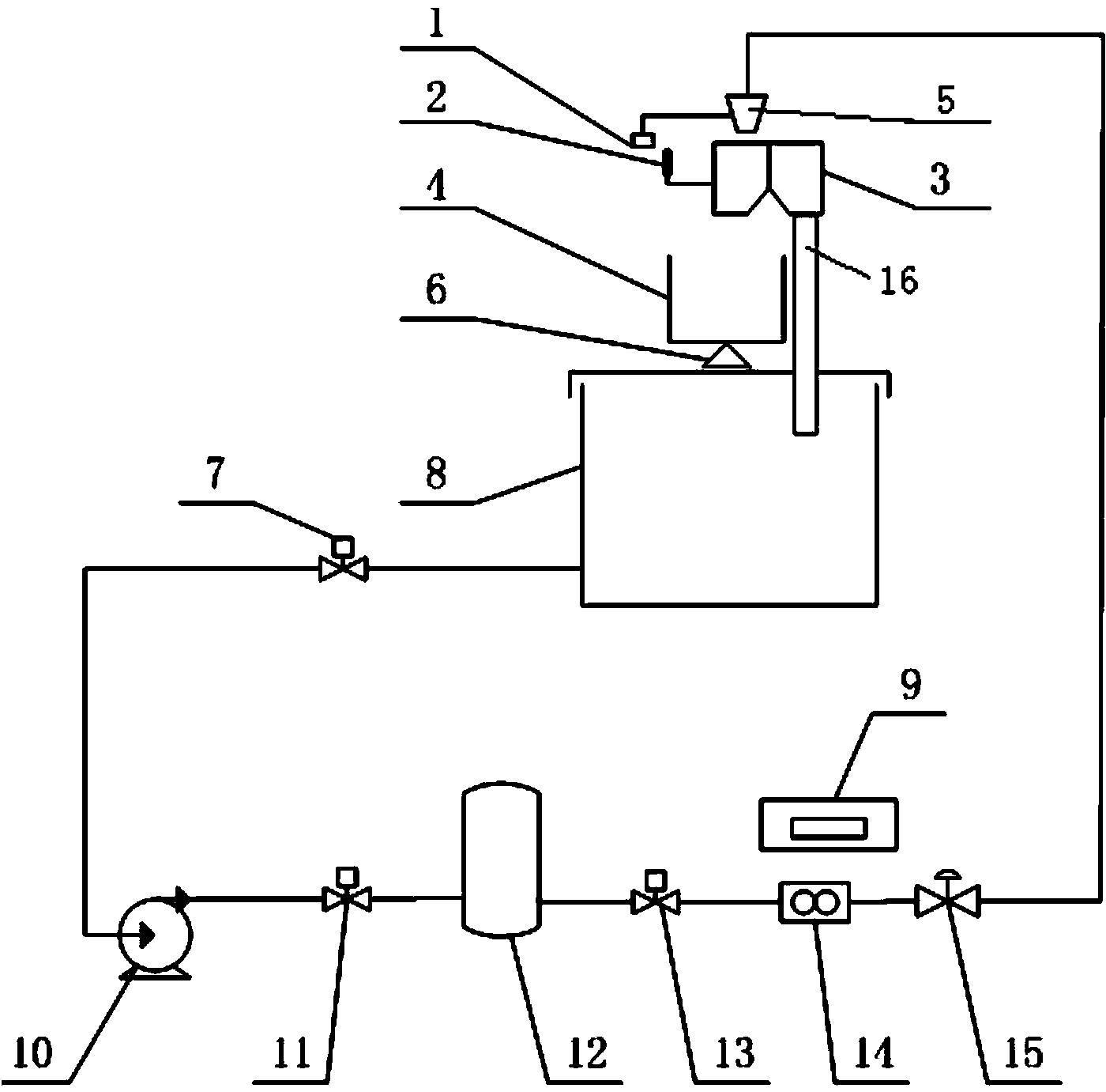
[0022] A pulse timing counting device for liquid flow verification according to the present invention, which is used in a liquid flow device, and a pulse timing counting device 9 is provided above the flow meter 14 of the liquid flow device;

[0023] Such as figure 1 As shown, the liquid flow device includes a circulating water tank 8, which is connected to a water pump 10 through a pipeline; the water pump 10 is connected to a surge tank 12 through a pipeline, and the surge tank 12 is connected to a flow meter 14 and a flow meter 14 through a pipeline. Connect the water outlet pipe 5 set above the commutator 2 through a pipeline; an electronic scale 6 is set above the circulating water tank 8, and a weighing water tank 4 is placed on the electronic scale 6, and next to the weighing water tank 4 is the circulating water tank inlet 16; the commutator 3 is set above the entrance of the weighing water tank 4 and the circulating water tank, the outlet pipe 5 is set above the commutato...

Embodiment 2

[0027] Using the pulse timing counting method of the pulse timing counting device for liquid flow verification described in Example 1, the steps are as follows:

[0028] First, fill the circulating water tank 8 with more than 80% water. After the weighing tank 4 is empty, the water is peeled. The commutator 5 makes the water flow to the circulating water tank 8. Open the pump inlet valve 7, the pump outlet valve 11, and the flow meter inlet valve 13 respectively. , After adjusting the flow through the water pump 10 and the regulating valve 15 to reach the verification value, the commutator 3 reverses to make the water flow into the weighing tank 4, and the shutter 1 on the commutator 3 blocks the photoelectric switch 2 to generate a trigger signal. The trigger signal is transmitted to the pulse timing and counting device 9 to start timing and counting. When the water in the weighing tank 4 reaches the predetermined quality, the commutator 3 reverses to stop timing and counting, an...


PUM


Abstract

The invention provides a pulse timing and counting device and method for liquid flow verification. A pulse timing and counting device is arranged above a flow meter of a liquid flow device and comprises a main controller; the main controller coordinates the work of external modules; the external modules comprise a timing and counting module, a communication module, a key input module, a level trigger module, a display module and an output module. A diverter diverts to enable water to flow into a weighing water tank, a blocking piece on the diverter blocks a photoelectric switch to generate a trigger signal, and the trigger signal is transmitted to the pulse timing and counting device to start to time and count; when the water in the weighing water tank reaches predetermined weight, the diverter diverts to stop timing and counting, and the weight, the time and the pulse count for weighing are recorded. By adopting the pulse timing and counting device and method, the synchronization of timing and counting of the flow verification device can be realized; meanwhile the diversion time difference of each diversion of the diverter can be detected.

Description

Technical field [0001] The invention belongs to the technical field of liquid flow or volume measurement, and specifically relates to a pulse timing counting device and method for liquid flow verification. Background technique [0002] Flow measurement is the most important part of measurement science and has been widely used in various fields. The flow standard device is a standard device for flow meter transmission, mainly based on the liquid flow device of the static mass method. [0003] In "JJG164-2000 Liquid Flow Device Verification Regulations", two methods are stipulated to verify the commutator, the stroke difference method and the flow meter method. The stroke difference method is to measure the commutator's switch-out and switch-in time, calculate their standard deviation and the time difference between switch-out and switch-in, and then calculate the uncertainty of the commutator. This method is relatively simple, convenient to implement, and widely used, but in the v...

Claims


Application Information

Patent Timeline
IPC IPC(8): G01F25/00G01R23/10G04G7/00
Inventor 吴佳灵孙海涛逯军唐永欣任闽何小兵王德志
Owner BEIJING AEROSPACE INST FOR METROLOGY & MEASUREMENT TECH
Why Eureka
Try Eureka