Light guide plate and backlight module using light guide plate

A technology of backlight module and light guide plate, applied in the field of light guide plate, can solve the problems of inability to meet the conditions of total reflection, increase the divergence angle of light, escape, etc., and achieve the effect of reducing side lighting phenomenon, increasing divergence angle and uniform transmission

Inactive Publication Date: 2015-02-11
YOUNG LIGHTING TECHNOLOGY INC
View PDF5 Cites 3 Cited by
  • Summary
  • Abstract
  • Description
  • Claims
  • Application Information

AI Technical Summary

Problems solved by technology

[0003] However, although these optical microstructures can make the light emitted by the light-emitting diodes uniformly diverge inside the light guide plate, while increasing the divergence angle of the light incident into the light guide plate, it is often easy to cause when the light enters the light guide plate. When the side surface cannot meet the total reflection condition, it escapes to the outside of the light guide plate, resulting in the problem of side brightness

Method used


Image

  • Light guide plate and backlight module using light guide plate
  • Light guide plate and backlight module using light guide plate
  • Light guide plate and backlight module using light guide plate

Examples


Embodiment Construction

[0037] The following descriptions of various embodiments refer to the accompanying drawings to illustrate specific embodiments in which the present invention can be practiced. The direction terms mentioned in the present invention, such as "up", "down", "front", "rear", "left", "right", etc., are only referring to the directions of the drawings. Accordingly, the directional terms are used to illustrate, not to limit, the invention.

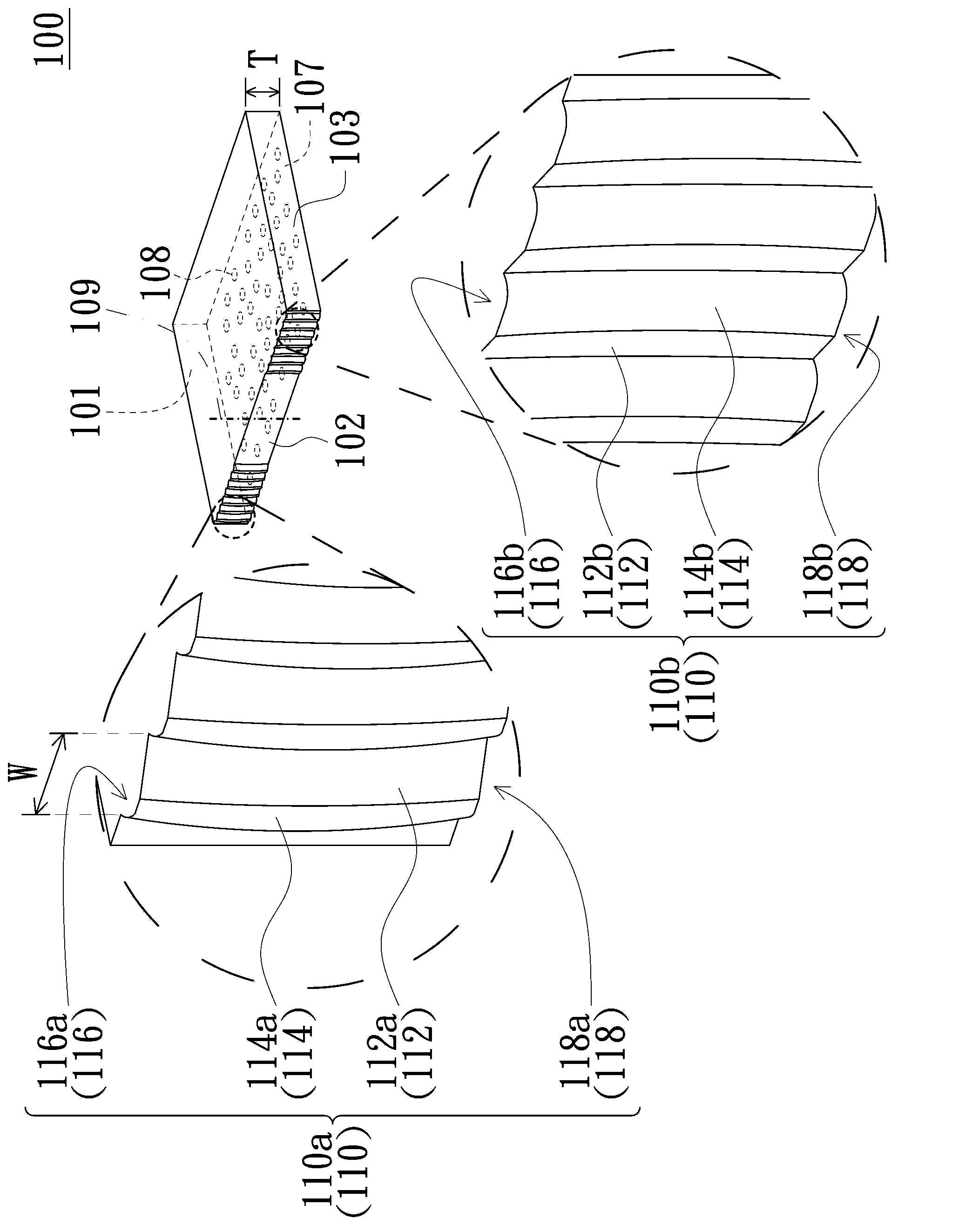
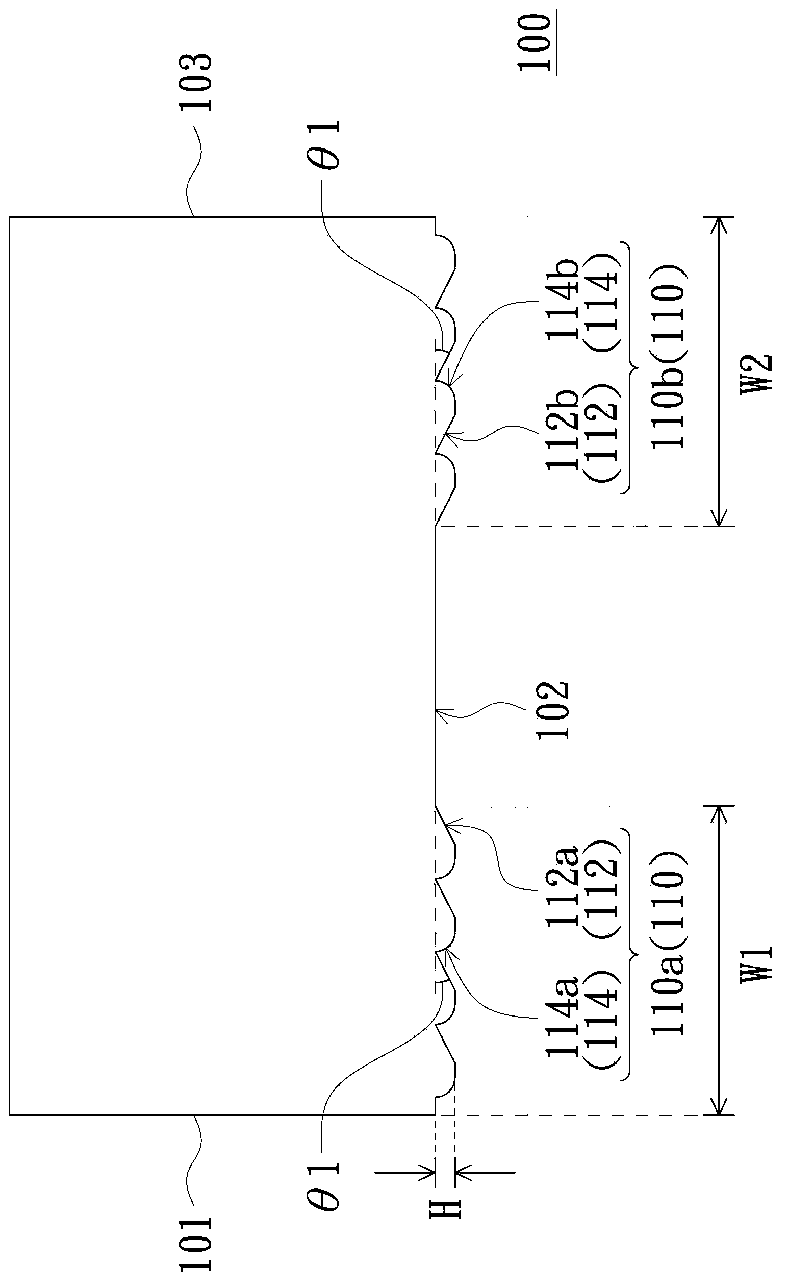
[0038] Figure 1A is a three-dimensional schematic diagram of a light guide plate in an embodiment of the present invention, Figure 1B then Figure 1A A top view of the light guide plate. Please also refer to Figure 1A and Figure 1B The light guide plate 100 has a light incident surface 102 , a first side surface 101 , a second side surface 103 , a light exit surface 105 and a bottom surface 107 opposite to the light exit surface. The light incident surface 102 has a plurality of strip optical microstructures 110, each strip optical microstr...


PUM


Abstract

A light guide plate includes a light incident surface, a light emitting surface, a bottom surface, a first lateral surface, and a second lateral surface. The light incident surface has a plurality of elongated optical microstructures, and each elongated optical microstructure has an inclined surface and a curved surface connected with each other. The light guide plate is capable of increasing uniformity and utilization rate of light beam emitting from the light guide plate. A backlight module using the light guide plate is also provided.

Description

technical field [0001] The present invention relates to a light guide plate, and in particular to a light guide plate with an optical microstructure on the light incident surface and a backlight module using the light guide plate. Background technique [0002] Light emitting diodes (light emitting diodes, LEDs) have become mainstream light sources of backlight modules at present. However, since the light-emitting diode is a point light source, the light emitted by it has strong directivity, so the light is often concentrated in a certain place to produce a bright spot. In order to improve this problem, the existing common practice is to design an optical microstructure on the light-incident surface of the light guide plate of the backlight module, so as to use the optical microstructure to change the traveling path of the light emitted by the light-emitting diode and make it evenly diverge. . [0003] However, although these optical microstructures can make the light emitt...

Claims


Application Information

Patent Timeline
Patent Type & Authority Applications(China)
IPC IPC(8): G02B6/00F21V8/00F21S8/00
CPCG02B6/002G02B6/0015G02B6/0016
Inventor 胡佳状
Owner YOUNG LIGHTING TECHNOLOGY INC
Why Eureka
Try Eureka