Coupler

A technology of couplers and mixed media, applied in the field of couplers, can solve problems such as coupling loss

Active Publication Date: 2016-11-23
HISENSE BROADBAND MULTIMEDIA TECH
View PDF3 Cites 4 Cited by
  • Summary
  • Abstract
  • Description
  • Claims
  • Application Information

AI Technical Summary

Problems solved by technology

However, since the spot shape and area of ​​the light emitted from the rectangular cross section are still different from those of the fiber cross section, the coupling loss still exists

Method used


Image

  • Coupler
  • Coupler
  • Coupler

Examples


Embodiment Construction

[0031] The following will clearly and completely describe the technical solutions in the embodiments of the present invention with reference to the accompanying drawings in the embodiments of the present invention. Obviously, the described embodiments are only some, not all, embodiments of the present invention. Based on the embodiments of the present invention, all other embodiments obtained by persons of ordinary skill in the art without creative efforts fall within the protection scope of the present invention.

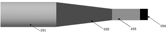
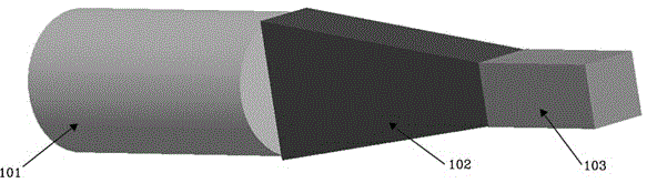
[0032] In the field of optical communication, the light emitted by the light-emitting unit needs to enter the optical fiber and propagate through the optical fiber. However, the modulation mechanism and packaging mechanism of the light-emitting unit make there is a certain space distance between the light-emitting unit and the optical fiber, and the light emitted by the light-emitting unit needs to pass through this space distance to enter the optical fiber; The de...


PUM


Abstract

The invention provides a coupler, relating to the optical communication field. The coupler comprises a first light spot zooming zone and a second light spot zooming zone; the first light spot zooming area comprises a first media and a second media packing the first media; a refractive index of the first medial is greater than a second refractive index of the second media; the first media comprises a square surface and a rectangle surface; light goes in and out of the first media through the square surface and the rectangle surface; the area of the rectangle surface is greater than that of the square surface; the second light spot zooming area is positioned on one side of the rectangle surface of the first media; the second light spot zooming area comprises hybrid medium and uniform medium, and the hybrid medium and the uniform medium are arranged by intervals; the hybrid media comprises a third media and a fourth media packing the third media; and the refractive index of the third media is greater than that of the fourth media. The coupler reduces energy loss during an optical coupling process.

Description

technical field [0001] The invention relates to the field of optical communication, in particular to a coupler. Background technique [0002] In the field of optical communication, due to the different cross-sectional shapes and areas of the optical fiber cross section and the planar dielectric waveguide, in order to improve the coupling efficiency of light between the optical fiber and the planar dielectric waveguide, a coupling is set between the optical fiber and the planar dielectric waveguide in the prior art. device. [0003] Since the propagation of light is reversible, now take light entering an optical fiber from a planar dielectric waveguide as an example. figure 1 A schematic diagram of a connection structure between a light emitting unit and an optical fiber provided in the prior art. Such as figure 1 As shown, a coupler 102 and a planar dielectric optical waveguide 103 are disposed between the optical fiber 101 and the light emitting unit 104 . The light emi...

Claims


Application Information

Patent Timeline
Patent Type & Authority Applications(China)
IPC IPC(8): G02B6/38
Inventor 张华
Owner HISENSE BROADBAND MULTIMEDIA TECH
Why Eureka
Try Eureka