Super-remote access, arrangement and video monitoring system for stage lamp

A technology of video monitoring system and stage lighting, which is applied in closed-circuit television system, transmission system, data exchange through path configuration, etc. It can solve the problems of inability to complete the setting and monitoring of intelligent dimming cabinets, inability to realize access, setting and monitoring functions, Problems that cannot be solved in time to achieve the effect of improving real-time control, reducing service costs, and ensuring life expectancy

Inactive Publication Date: 2015-02-11
RGB LIGHTING EQUIP
View PDF3 Cites 3 Cited by
  • Summary
  • Abstract
  • Description
  • Claims
  • Application Information

AI Technical Summary

Problems solved by technology

[0002] The existing network dimming control system is generally composed of intelligent dimming cabinets and switches. The intelligent dimming cabinets are located in the internal LAN. Therefore, when it is necessary to set and monitor the intelligent dimming cabinets, it must On-site operation and monitoring of the light cabinet or in the local area network where the intelligent dimming cabinet is located. Once leaving the local area network, the setting and monitoring of the intelligent dimming cabinet cannot be completed. If there is a failure in the dimming cabinet or a problem with the operation of the stage lights, it cannot be solved in time
That is to say, in the existing dimming control system, all network control is limited to the local internal network, and it is impossible to access, set and monitor the dimming control system anytime, anywhere, using any public network, and at the same time realize remote control. Training and Operating Instructions

Method used


Image

  • Super-remote access, arrangement and video monitoring system for stage lamp
  • Super-remote access, arrangement and video monitoring system for stage lamp

Examples


Embodiment Construction

[0018] The present invention will be described in further detail below in conjunction with the accompanying drawings and specific embodiments.

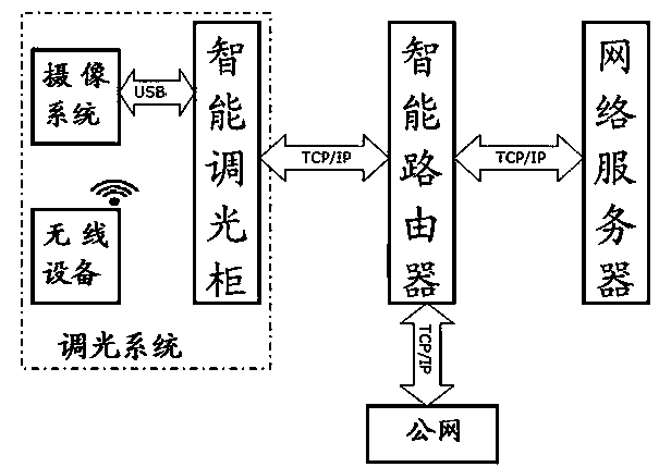
[0019] Such as figure 1 As shown, the ultra-remote access, setting and video monitoring system of the present invention includes an intelligent dimming cabinet, an intelligent router and a network server. The intelligent dimming cabinet is located in the internal local area network, and the input end of the intelligent router is connected to the output end of the intelligent dimming cabinet. , the output end of the intelligent router is connected to the external public network, and the network server is bound to the domain name IP address of the intelligent dimming cabinet in the internal LAN to realize the seamless connection between the internal LAN and the public network.

[0020] The working principle of the present invention is: the intelligent dimming cabinet receives the lighting parameter information, encodes and packages it, ...


PUM


Abstract

The invention provides a super-remote access, arrangement and video monitoring system for a stage lamp. The system comprises an intelligent light modulation cabinet, an intelligent router and a network server which are arranged in an internal local area network. The input end of the intelligent router is connected with the output end of the intelligent light modulation cabinet, and the output end of the intelligent router is connected with a public network; the intelligent light modulation cabinet receives light parameter information, encodes and packs the information and then sends the information to the intelligent router, and the intelligent router performs conversion on the light parameter information for sending to the public network; and the public network encodes and packs stage lamp working state information and then sends the stage lamp working state information to the intelligent light modulation cabinet through the intelligent router, the intelligent light modulation cabinet modifies, stores and displays the state information after unpacking and decoding, and a network server binds the domain name IP address of the intelligent light modulation cabinet in the internal local area network. According to the invention, real-time access, arrangement and monitoring of the operation state of the intelligent light modulation cabinet in the local area network can be realized in a super-remote mode through the public network.

Description

technical field [0001] The invention relates to the application of stage lights, in particular to a dimming control system for stage lights. Background technique [0002] The existing network dimming control system is generally composed of intelligent dimming cabinets and switches. The intelligent dimming cabinets are located in the internal LAN. Therefore, when it is necessary to set and monitor the intelligent dimming cabinets, it must On-site operation and monitoring of the light cabinet or in the local area network where the intelligent dimming cabinet is located. Once leaving the local area network, the setting and monitoring of the intelligent dimming cabinet cannot be completed. If the dimmer cabinet fails or the stage lights have problems, they cannot be solved in time. That is to say, in the existing dimming control system, all network control is limited to the local internal network, and it is impossible to access, set and monitor the dimming control system any...

Claims


Application Information

Patent Timeline
Patent Type & Authority Applications(China)
IPC IPC(8): H04L29/08H04N7/18H04L12/46
CPCH04L67/025H04N7/18
Inventor 何首锋
Owner RGB LIGHTING EQUIP
Why Eureka
Try Eureka