Mini-tiller

A technology of micro-tiller and tiller, applied in the field of micro-tiller, can solve the problems of inconvenient transfer, cumbersome operation, time-consuming and labor-intensive, etc., and achieve the effects of convenient transfer, convenient storage and operation, and avoiding interference.

Active Publication Date: 2015-02-18
重庆华世丹动力科技有限公司
View PDF5 Cites 4 Cited by
  • Summary
  • Abstract
  • Description
  • Claims
  • Application Information

AI Technical Summary

Problems solved by technology

When the tiller is not in use, since the lower end of the resistance cultivator will exceed the wheels, it will be very inconvenient when transporting on the road, so it is necessary to manually raise the resistance cultivator, and the next time it is used for tilling the soil It needs to be adjusted back down, the operation is very cumbersome, time-consuming and labor-intensive

Method used


Image

  • Mini-tiller
  • Mini-tiller
  • Mini-tiller

Examples


Embodiment Construction

[0067] The implementation of the present invention will be illustrated by specific specific examples below, and those skilled in the art can easily understand other advantages and effects of the present invention from the contents disclosed in this specification.

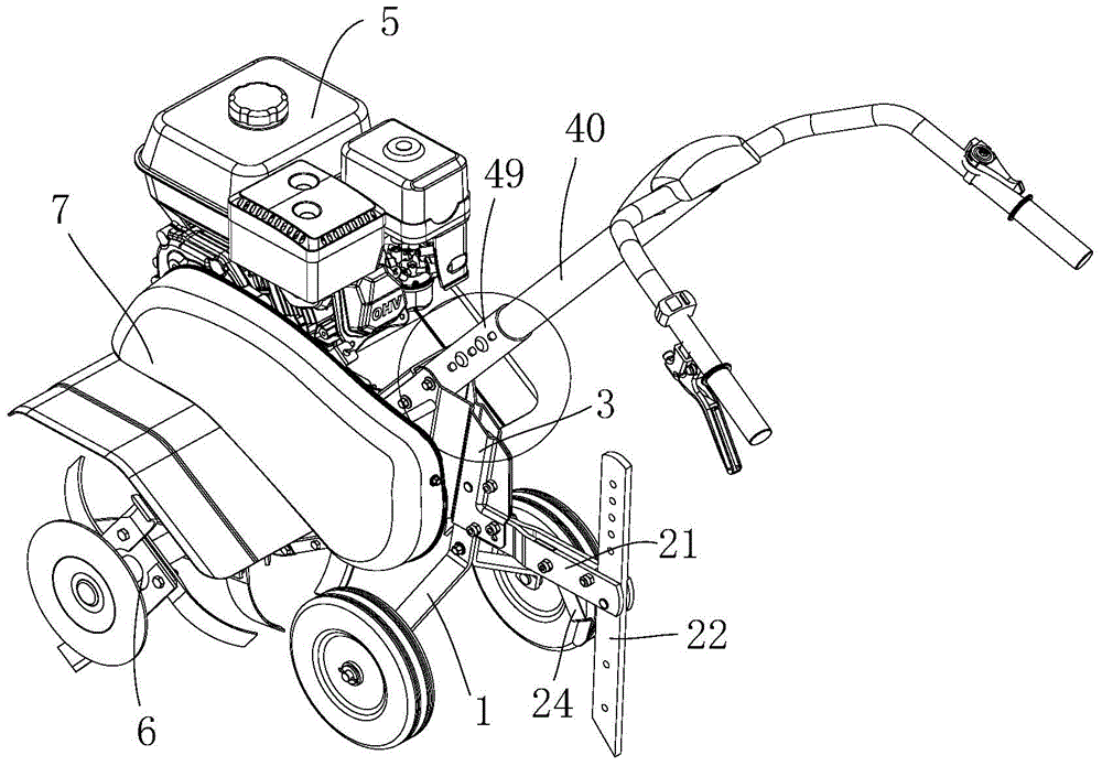
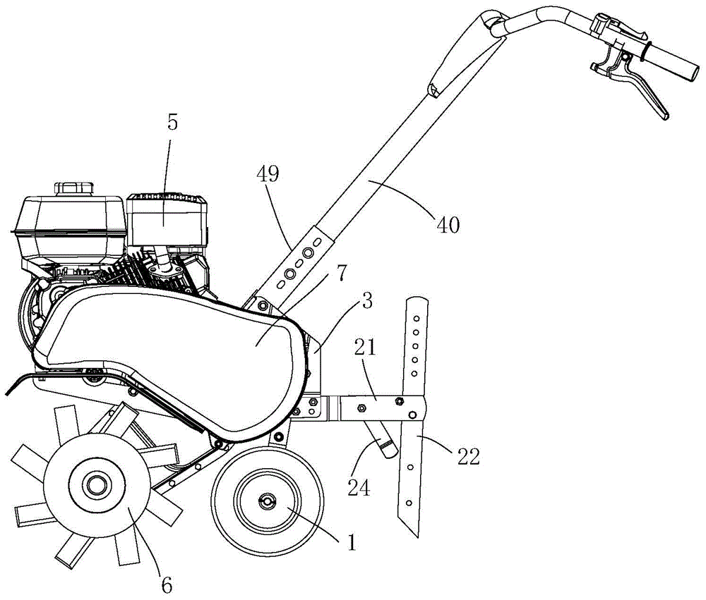
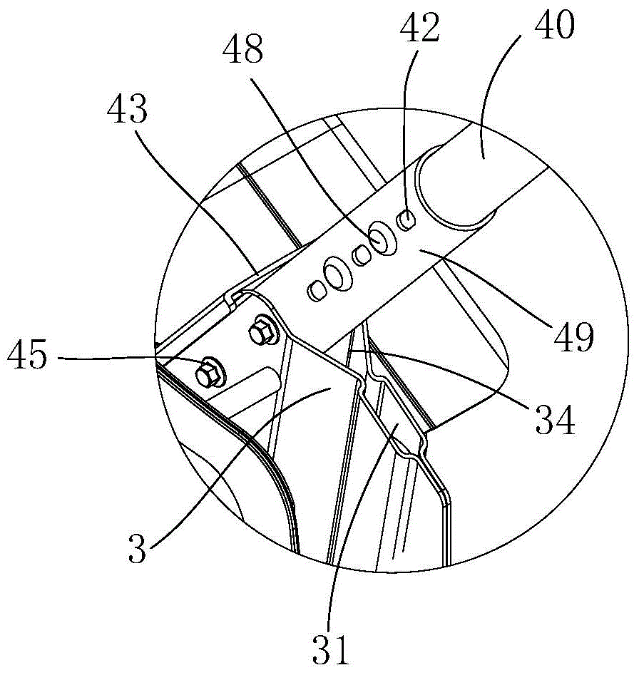
[0068] Such as Figure 1 to Figure 5 As shown, the present invention provides a micro tillage machine, including a frame and a motor assembly 5 installed on the frame, a support frame 3, a tiller assembly 6, a walking mechanism 1, a handrail assembly and a protection assembly 7, Described walking mechanism comprises traveling wheel 16 and support assembly 1, and support assembly 1 comprises first support member 11, second support member 12 and the 3rd support member 13, and first support member 11 is detachably connected with support frame 3, and second Both the upper end of the support member 12 and the upper end of the third support member 13 are connected to the lower end of the first support member 11, the secon...


PUM


Abstract

The invention provides a mini-tiller which comprises a frame, a power assembly, a supporting rack, a plowing cutter component, a travelling mechanism, a handrail component and a protecting component, wherein the travelling mechanism comprises travelling wheels and a bracket component; the bracket component comprises a first supporting member, a second supporting member and a third supporting member; the first supporting member is detachably connected with the supporting rack; the upper end of the second supporting member and the upper end of the third supporting member are both connected with the lower end of the first supporting member; the second supporting member is inclined to the left lower side of the first supporting member; the third supporting member is inclined to the right lower side of the first supporting member; the upper end of the second supporting member and the lower end of the third supporting member are respectively connected with one travelling wheel. According to the invention, the bracket component and the supporting rack are detachably connected, so that the bracket component and the supporting rack can be conveniently mounted and dismounted and the mini-tiller can be for conveniently dismounted, contained and packed; the space heights at the upper end of the second supporting member and the lower side of the third supporting member are higher; the condition of interference between the traditional horizontal wheel shaft and the raised ground during a traveling process is avoided; tools and the travelling wheels need not be exchanged; the mini-tiller is convenient to transfer.

Description

technical field [0001] The invention relates to the technical field of agricultural machinery, in particular to a tiller. Background technique [0002] With the vigorous support and development of agricultural mechanization, the use of tillage machines is becoming more and more extensive. Existing tiller, its traveling wheel support usually is made of mutually vertical axle and support, and the two ends of wheel axle are connected traveling wheel, and support is connected with the supporting frame of power assembly, and the traveling wheel support of this structure, is with the power assembly. It is fixedly connected, and the height of the whole tiller cannot be adjusted through the walking wheel bracket; and the tool and the walking wheel share the axle, and the tool is installed on the wheel axle during work. The operation is cumbersome, time-consuming and labor-intensive. The handrail tube is a holding mechanism for the operator to carry out work such as pushing and tur...

Claims


Application Information

Patent Timeline
Patent Type & Authority Applications(China)
IPC IPC(8): A01B33/02A01B33/08A01B69/06
Inventor 窦思勇王卫兵
Owner 重庆华世丹动力科技有限公司
Why Eureka
Try Eureka