A lock-off system for front panels of furniture drawers

A front panel and lock-off technology, applied in the field of lock-off systems, can solve the problems of unsatisfactory users, easy to shake, and the adjustment method of the drawer panel is not convenient for users to use daily.

Active Publication Date: 2016-08-31
伍志勇
View PDF8 Cites 0 Cited by
  • Summary
  • Abstract
  • Description
  • Claims
  • Application Information

AI Technical Summary

Problems solved by technology

When the height of the panel of the drawer in this structure is relatively high, it is extremely easy to shake, which makes the user unsatisfied; and the connecting piece on the panel needs to be connected with the adjustment seat at the same time to fix the panel, which makes it inconvenient for the user to use, and the assembly after assembly The adjustment method of the drawer panel is not convenient for the daily use of the user

Method used


Image

  • A lock-off system for front panels of furniture drawers
  • A lock-off system for front panels of furniture drawers
  • A lock-off system for front panels of furniture drawers

Examples


no. 1 example

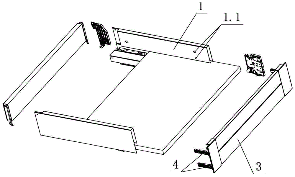
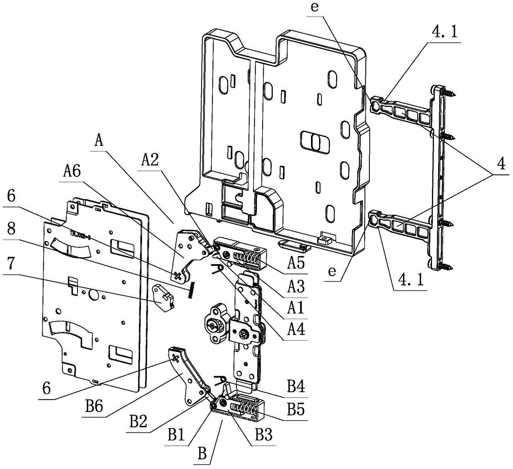
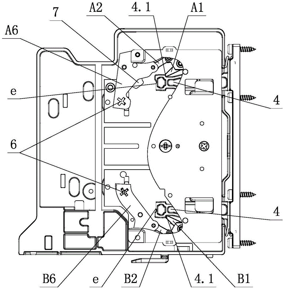
[0032] See Figure 1-Figure 12 , The lock and release system for the front panel of a furniture drawer includes a fixing device arranged on the side plate 1. The front panel 3 is connected to the fixing device through two or more connecting elements 4, and the fixing device is provided with more than two sets of In the locking and disengaging mechanism for locking and separating the connecting element 4, the locking and disengaging mechanism is provided with a finger-shaped element and an unlocking element that is drivingly connected to the finger-shaped element. The finger-shaped element is locked and separated from the connecting element 4 by the movement of the unlocking element. The two or more sets of locking and disengaging mechanisms are relatively independent and arranged up and down, and do not interfere with each other when they are locked and disengaged with the respective connecting elements 4; at least one of the locking and disengaging mechanisms is provided with a ...

no. 2 example

[0047] See Figure 13 , Figure 14 , The present lock and release system for the front panel of a furniture drawer is different from the first embodiment in that the first and second unlocking elements have a common unlocking part, and the unlocking part is driven by a tool to act on the first 1. On the second unlocking element, the finger-shaped element is separated from the connecting element 4 to realize the separation of the front panel 3 and the side panel 1.

[0048] Specifically, the fixing device is provided with an unlocking part, the unlocking part is provided with a pushing element 5, and the pushing element 5 is provided with a pushing action part 5.1 for the action of a tool. The pushing action part 5.1 is acted on by the tool, and the pushing element 5 is driven together. Act on the first unlocking element A6 and the second unlocking element B6 of the first and second locking and disengaging mechanisms in sequence, so that the first finger-shaped element A1 and the s...


PUM


Abstract

The invention relates to a locking and disengaging system for a drawer front surface plate of furniture. The locking and disengaging system comprises a fixing device, wherein the fixing device is arranged on side plates, a front surface plate is connected with the fixing device through more than two connecting elements, more than two locking and disengaging mechanisms are arranged on the fixing device, are used for locking and disengaging the connecting elements, and are respectively provided with a finger-shaped element and an unlocking element, each unlocking element is in transmission connection with the corresponding finger-shaped element, each finger-shaped element is locked with and disengaged from the corresponding connecting element through the movement of the corresponding unlocking element, the locking and disengaging mechanisms are relatively independently and vertically arranged, and are free from mutual interference when the locking and disengaging mechanisms are respectively in locking and disengaging matching with the corresponding connecting element, and at least one locking and disengaging mechanism is provided with a retaining element with elastic loading. By improving the structure, the locking and disengaging system has the characteristics that the structure is simple and reasonable, the property is reliable, the connection is firm, the manufacturing cost is low, the detachment and installation are quick and convenient, the flexibility is high, the application range is wide, and the practicality is high.

Description

Technical field [0001] The invention relates to a furniture drawer, in particular to a lock and release system for the front panel of the furniture drawer. Background technique [0002] Chinese Patent Document No. CN 101224065A disclosed on July 23, 2008 a panel locking and adjusting device for a drawer with a sliding rail, which includes a sliding rail connected to the drawer, and the panel of the drawer is connected to the adjusting seat through a connector. The adjusting seat is provided with a guide groove for the connecting piece to slide, and a panel locking mechanism is arranged in the guide groove. The panel locking mechanism includes an eccentric cam arranged on the adjusting seat. The other end of the eccentric cam is hinged with the guide block through a connecting rod. One end is hinged on the guide block through a pin shaft, the torsion spring is sleeved on the pin shaft, one end is connected to the swing rod, the other end is connected to the guide block or the adju...

Claims


Application Information

Patent Timeline
Patent Type & Authority Patents(China)
IPC IPC(8): A47B88/00
Inventor 伍志勇
Owner 伍志勇
Why Eureka
Try Eureka