Eureka AIR delivers breakthrough ideas for toughest innovation challenges, trusted by R&D personnel around the world.

Purification and dust removal device

A dust removal device and a combined technology, applied in the field of printing and dyeing industry, can solve the problems of uneven electric field strength of the dust suction mechanism, easy vibration of the cathode line, small effective area, etc. Effect

Inactive Publication Date: 2015-02-18
福建省沃特宝环保科技有限公司
View PDF8 Cites 4 Cited by
  • Summary
  • Abstract
  • Description
  • Claims
  • Application Information

AI Technical Summary

Problems solved by technology

[0004] The technical problem to be solved by the present invention is to provide a purification and dust removal device to solve the problems of uneven electric field strength, small effective area, easy shaking of the cathode line, and easy discharge and fire of the dust suction mechanism in the prior art.

Method used


Image

  • Purification and dust removal device
  • Purification and dust removal device
  • Purification and dust removal device

Examples

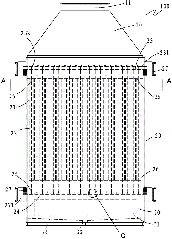

Embodiment Construction

[0025] The preferred embodiments of the present invention will be further described below in conjunction with the accompanying drawings.

[0026] see Figure 1 to Figure 7 , a purification and dust removal device, the box 100 of the purification and dust removal device includes an upper box 10, a middle box 20 and a lower box 30, the upper box 10 is provided with an air outlet 11, and the lower box The side wall of 30 is provided with an air inlet 31, and the air inlet 31 is provided with at least one defogging plate 311, please refer to Figure 6 and Figure 7 , the defogging plate 311 is composed of a frame 3111 and a plurality of defogging sheets 3112, the upper and lower ends of each of the defogging sheets 3112 are fixed on the frame 3111, and the defogging sheets 311 are composed of two The two surfaces are integrally formed and form an included angle α, and the range of the included angle is 90°≤α≤160°. When the exhaust gas passes through the defogging plate, the wate...


PUM


Abstract

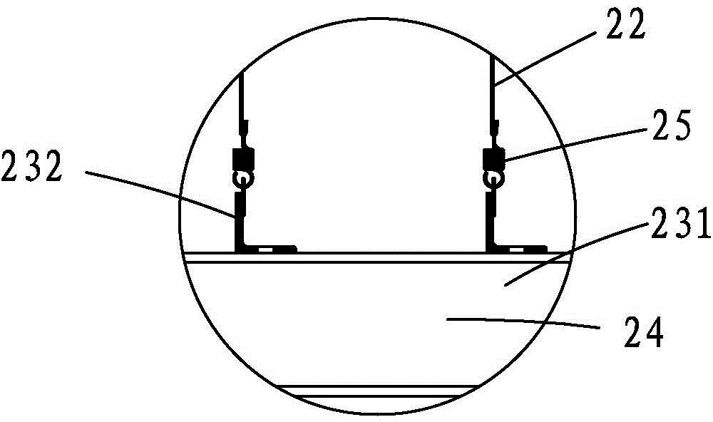
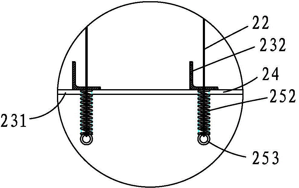
The invention provides a purification and dust removal device. A plurality of dust suction pipes are vertically distributed in a box body of the purification and dust removal device; cathode lines penetrate through the dust suction pipes respectively and are fixed by an upper frame and a lower frame; the upper end parts of the cathode lines are fixed on the upper frame, and the lower end parts of the cathode lines are fixed on the lower frame; the upper frame and the lower frame are both fixed on the box body; the upper frame or the lower frame is connected with a high-voltage power supply system through a wire. The dust suction pipes are arranged to greatly enlarge the dust collection area; the cathode lines penetrate through the centers of the dust suction pipes, so that the internal part of each dust suction pipe forms a high electric field which is uniform in strength, large in onset area, and capable of rectifying the exhaust gas when the exhaust gas passes through each of the dust suction pipes; the cathode lines are fixed through elastic elements, so that the cathode lines can be tensioned tightly; the elastic elements are low in wind resistance and low in possibility of swing, so that the cathode lines are better in stability.

Description

【Technical field】 [0001] The invention relates to the field of printing and dyeing industry, in particular to a purification and dust removal device for treating waste gas. 【Background technique】 [0002] The printing and dyeing industry will produce a large amount of waste gas during the production process. If these waste gases are directly discharged into the atmosphere, they will cause serious pollution to the atmospheric environment, especially the waste gas from the setting machine, which contains oil mist, fibers, water vapor, dust and SO 2 , N 2 o X and other harmful gases, therefore, the waste gas must be purified. [0003] The invention patent with the publication number of 103817005A and the publication date of 2014-05-28 "A Plate-Tube Vertical Flow Wet High-Efficiency Electrostatic Precipitator" discloses a plate-tube vertical flow wet-type high-efficiency electrostatic precipitator, including the shell, which is characterized in that The housing is provided wi...

Claims


Application Information

Patent Timeline
Patent Type & Authority Applications(China)
IPC IPC(8): B03C3/04B03C3/34
Inventor 王绍伟栗维清王兆浪
Owner 福建省沃特宝环保科技有限公司
Why Eureka
Eureka Blog
Learn More