Master plate clamp of vertical type milling machine

A vertical milling machine, relying on the template technology, applied in the direction of clamping, manufacturing tools, copying process control system, etc., can solve the problems of inaccurate tool centering, decreased machining accuracy, and damaged tools, so as to achieve simple structure and improve machining accuracy , the effect of increasing productivity

Inactive Publication Date: 2015-02-18
AMPHENOL CHANGZHOU ELECTRONICS
View PDF0 Cites 1 Cited by
  • Summary
  • Abstract
  • Description
  • Claims
  • Application Information

AI Technical Summary

Problems solved by technology

[0002] Vertical milling machine has a wide range of applications in mechanical processing. It is used to process various required parts or workpieces. When processing certain curved grooves, it is often necessary to use a template to make the longitudinal direction of the milling machine table The feed is decomposed into the relative lateral motion between the processed workpiece and the tool to achieve the purpose of processing, so a special template and template fixture are needed to achieve it, and the existing template fixture is used when the tool is lowered. It is easy to produce relative sliding between the seats, and the centering of the tool is not accurate, resulting in a decrease in machining accuracy and easy damage to the tool due to shaking

Method used


Image

  • Master plate clamp of vertical type milling machine

Examples


Embodiment Construction

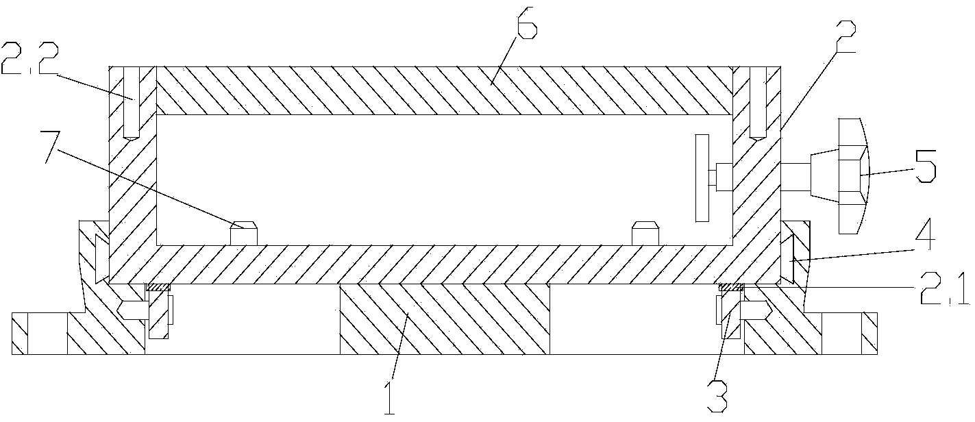
[0012] Such as figure 1 The vertical milling machine shown in the formwork fixture includes the base 1 and the U-shaped sliding seat 2 that are movably connected to the base 1. The top surface of the base 1 is provided with a fixing plate connected to the U-shaped sliding seat 2. The base 1 and the milling machine table are connected by screws. Fixed, gear 3 and chute 4 are provided on the inner side of the fixed plate, rack 2.1 matched with the gear 3 is provided at the opposite position on the bottom surface of U-shaped slide seat 2, and limit blocks are provided at both ends of rack 2.1, U-shaped slide seat 2 The outer walls of the vertical plates on both sides are provided with protrusions that match the chute, and the vertical plates on one side are also provided with fastening bolts 5, and the top surfaces of the vertical plates on both sides are also provided with threads that are detachably connected to the backing plate 6 Holes 2.2, U-shaped sliding seat 2 are provide...


PUM


Abstract

The invention belongs to the technical field of mechanical processing fixtures, and in particular relates to a master plate clamp of a vertical type milling machine. The master plate clamp comprises a base and a U-shaped sliding seat movably connected with the base, wherein a fixed plate connected with the U-shaped sliding seat is arranged on the top surface of the base; gears and sliding chutes are arranged on the inner side of the fixed plate; racks matched with the gear are arranged opposite to the bottom surface of the U-shaped sliding seat; bulges matched with the sliding chutes are arranged on the outer walls of vertical plates on two sides of the U-shaped sliding seat; a fastening bolt is also arranged on the vertical plate on one side; threaded holes detachably connected with a master plate are also formed in the top surfaces of the vertical plates on the two sides; limiting nails are arranged on the front side and the rear side of the sliding seat in the sliding direction. When a cutter works, the position of the sliding seat can be locked, so that the cutter and a workpiece cannot generate relative sliding; therefore, the processing precision is improved, and the cutter can be protected from damage.

Description

technical field [0001] The invention belongs to the technical field of machining fixtures, in particular to a template fixture for a vertical milling machine. Background technique [0002] Vertical milling machine has a wide range of applications in mechanical processing. It is used to process various required parts or workpieces. When processing certain curved grooves, it is often necessary to use a template to make the longitudinal direction of the milling machine table The feed is decomposed into the relative lateral motion between the processed workpiece and the tool to achieve the purpose of processing, so a special template and template fixture are needed to achieve it, and the existing template fixture is used when the tool is lowered. It is easy to produce relative sliding between the seats, and the centering of the tool is not accurate, resulting in a decrease in machining accuracy and easy damage to the tool due to shaking. Contents of the invention [0003] The...

Claims


Application Information

Patent Timeline
Patent Type & Authority Applications(China)
IPC IPC(8): B23Q3/06B23Q35/42
CPCB23Q35/46B23Q2735/002
Inventor 陆尧谭礼旗王世艮王焕刚
Owner AMPHENOL CHANGZHOU ELECTRONICS
Why Eureka
Try Eureka