Horizontal turning system for bridge construction

A bridge construction and horizontal technology, which is applied in the direction of bridges, bridge construction, erection/assembly of bridges, etc., can solve the problems of small movable space, unstable force, detachment and other problems of the upper ball strand, and achieve the problem of trembling, ensuring safety, cost reduction effect

Active Publication Date: 2015-02-18
中铁大桥局集团第六工程有限公司
View PDF9 Cites 16 Cited by
  • Summary
  • Abstract
  • Description
  • Claims
  • Application Information

AI Technical Summary

Problems solved by technology

[0007] (1) The swivel system must be counterweighted at one end of the beam before the swivel. At this time, the two swivel legs located on the longitudinal centerline of the main girder and the lower ball joint are on the same line, and the two swivel The force on the support feet is not uniform, causing one of the swivel legs to break away from the ring slide, and the other swivel leg to contact the ring slide. When the other legs are assumed to be suspended, the upper ball hinge and the ring slide It presents a two-point force state. Due to the instability of the force on the two points and the influence of the moment caused by the unbalanced pressure and weight on the left and right sides of the bridge, during the rotation process of the swivel system, it is easy to cause the swivel system to rotate along the longitudinal axis of the beam body. Poor stability
[0008] (2) There is a booster reaction seat on the annular slideway, and the mass of the booster reaction seat is relatively large. It is difficult to construct the booster reaction seat on the annular slideway at the top of the cap; The seat is located between the upper turntable and the lower turntable. Due to the large volume of the booster reaction seat, it will take up a lot of space, so that the activity space for the upper ball winch and the lower ball winch is small. Therefore, the booster reaction seat is practical It is difficult to use during construction, and the existing swivel system is difficult to achieve boosting

Method used


Image

  • Horizontal turning system for bridge construction
  • Horizontal turning system for bridge construction

Examples


Embodiment Construction

[0023] The present invention will be described in further detail below in conjunction with the accompanying drawings and embodiments.

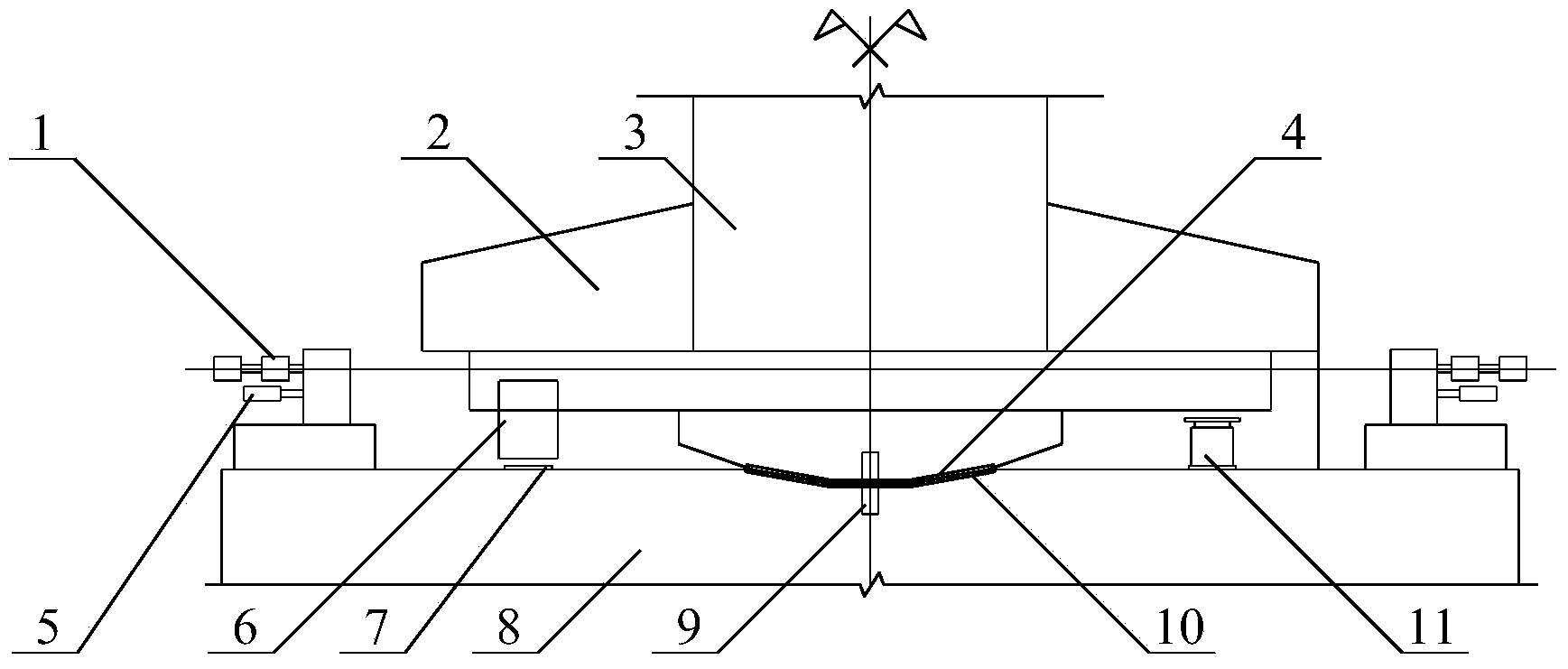
[0024] see figure 1 As shown, the embodiment of the present invention provides a horizontal swivel system for bridge construction, including an upper turntable 2 and a lower turntable 8 oppositely arranged, the upper turntable 2 is set at the bottom of the pier 3, and the lower turntable 8 is set at the bottom of the cap On the top, the bottom of the upper turntable 2 is fixed with an upper ball joint 4, and the top of the lower turntable 8 is fixed with a lower ball joint 10 used in conjunction with the upper ball joint 4, and the upper ball joint 4 and the lower ball joint 10 are connected by a positioning pin 9 .

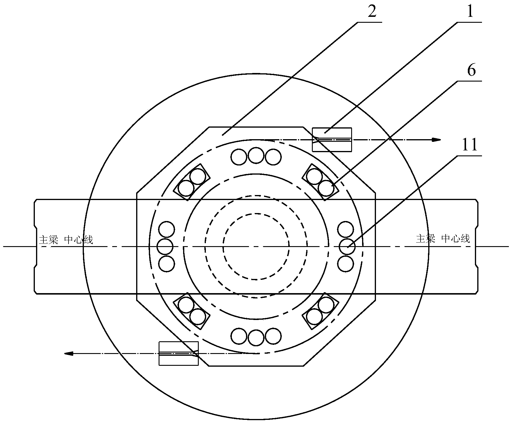
[0025] The bottom of the upper turntable 2 is provided with 4 supporting feet 6, and the 4 supporting feet 6 are evenly distributed on the circle centered on the upper turntable 2, and the angle between the connecting line of th...


PUM


Abstract

The invention discloses a horizontal turning system for bridge construction, and relates to the field of bridge turning construction. The horizontal turning system comprises an upper turning disc and a lower turning disc which are arranged oppositely, wherein an upper spherical hinge is fixedly connected to the bottom of the upper turning disc; a lower spherical hinge is fixedly connected to the top of the lower turning disc; four support feet are arranged at the bottom of the upper turning disc; the four support feet are uniformly distributed on the circumference which takes the upper turning disc as the center; an included angle of 45 degrees is formed between a connecting line of two opposite support feet and the central line of a main beam; two counter-force bases and an annular slideway used in match with the support feet are arranged on the top of the lower turning disc; the counter-force bases are positioned on the outer side of the annular slideway; the counter-force bases are externally tangent to the upper turning disc; the distance between the two counter-force bases is equal to the diameter of the upper turning disc; traction devices and pull assisting devices are arranged at the tops of the counter-force bases. Three-point support is formed by the lower spherical hinge and two support feet on stress sides of a beam body, so that relatively good stability is achieved; as the hoisting weight of a jack is relatively small, the cost is effectively lowered.

Description

technical field [0001] The invention relates to the field of bridge swivel construction, in particular to a horizontal swivel system for bridge construction. Background technique [0002] The swivel system is an auxiliary device for bridge erection, which is usually used in situations where it is difficult to achieve bridge erection with traditional construction. [0003] When the swivel system is used for bridge erection, the pouring of the main body of the bridge is usually completed at the predetermined position, and then the main girder is rotated to the design position through the swivel system, and finally the closing section of the bridge is poured to realize the construction of the main bridge. With the increase of the span of the bridge, the weight of the main girder has developed from the early kiloton level to the current 10,000-ton level. [0004] The existing swivel system usually includes a lower turntable on the top of the cap and an upper turntable on the bo...

Claims


Application Information

Patent Timeline
Patent Type & Authority Applications(China)
IPC IPC(8): E01D21/08
CPCE01D21/08
Inventor 彭建萍梁新礼杨仁恒陈南宁刘卫松万建桥李小波程沙平
Owner 中铁大桥局集团第六工程有限公司
Why Eureka
Try Eureka