
Telescopic transmission shaft

A technology of drive shaft and telescopic shaft, which is applied in the direction of buildings, building types, and buildings where cars are parked. It can solve the problems that the pick-and-place mechanism cannot pick and place low-chassis vehicles, the underground garage is inconvenient, and the car is taken out, and the structure is simple. Simplification, increased reliability, and good synchronization

Active Publication Date: 2015-02-18
泊易达停车设备有限公司
View PDF13 Cites 0 Cited by
  • Summary
  • Abstract
  • Description
  • Claims
  • Application Information

AI Technical Summary

Problems solved by technology

[0003] In the push-type underground three-dimensional parking garage, because it is necessary to complete the pick-and-place action of several tons of vehicles, the mechanism for picking and placing vehicles is relatively large. With the development of automobile technology, there are more and more low-chassis vehicles. The release mechanism cannot complete the pick-and-place work for low-chassis vehicles, especially when the tires of the cars stored in the garage are deflated, the pushed platform cannot take the car out, and may even cause damage to the vehicle, which brings great benefits to the popularization of underground garages. It is very inconvenient. There are many models with different wheelbases, which is a big challenge for mechanical garages. Now some garages have great limitations, especially low-floor sports cars, large off-road vehicles and commercial vehicles. If you blindly pursue The push platform is lightweight, suitable for sports cars with low chassis

Method used


Image

  • Telescopic transmission shaft
  • Telescopic transmission shaft
  • Telescopic transmission shaft

Examples


Embodiment Construction

[0020] The present invention will be further described in detail below in conjunction with the accompanying drawings and specific embodiments.

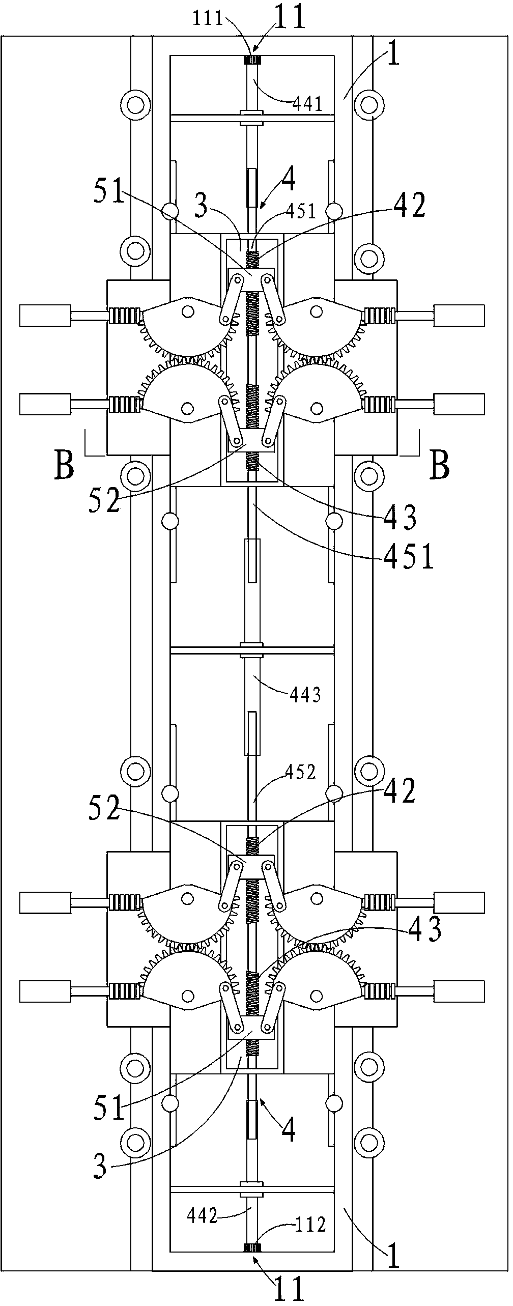
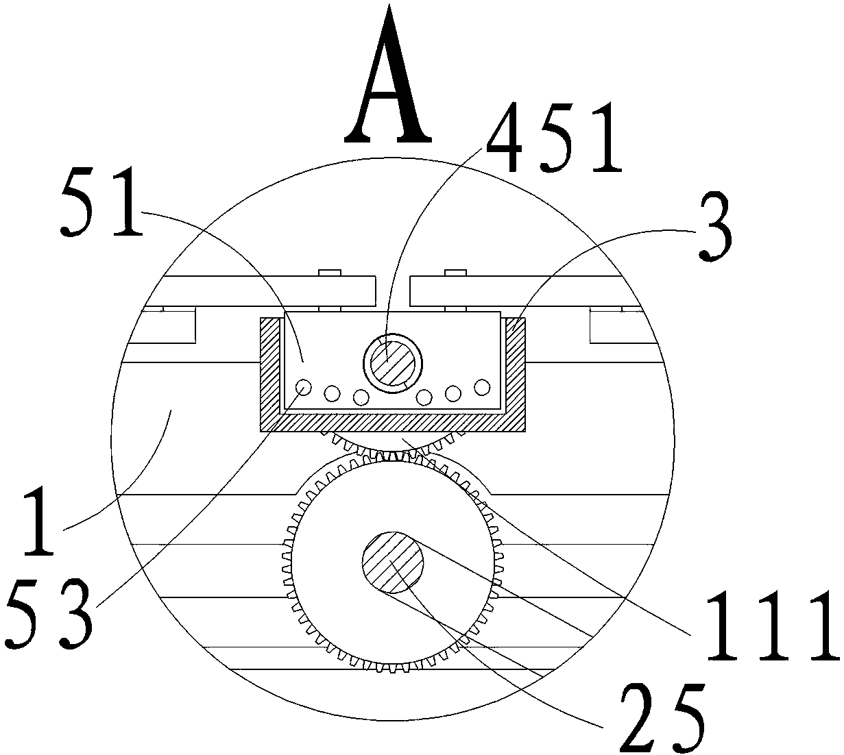
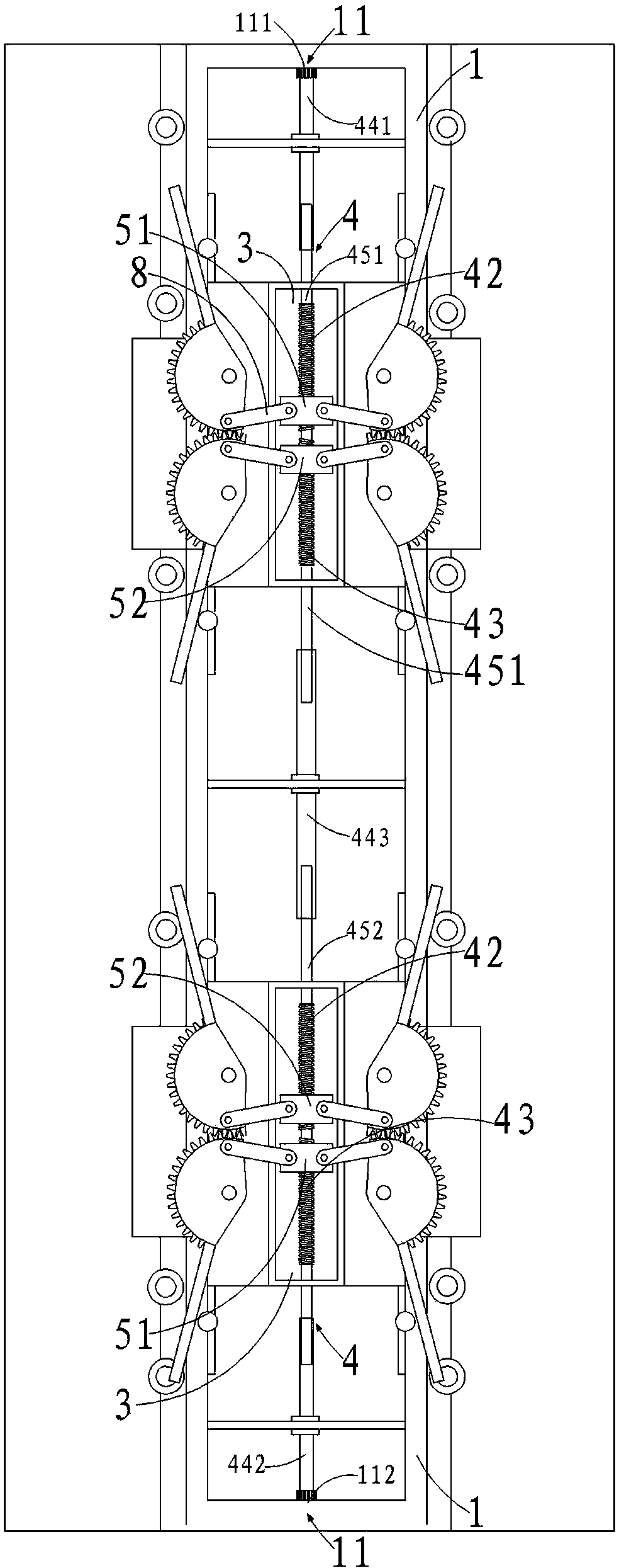
[0021] See attached Figures 1 to 5 , a telescopic transmission shaft in this embodiment includes an upper ring beam 1 and a telescopic shaft 4 that runs through the left and right ends of the upper ring beam 1. The telescopic shaft 4 sequentially includes: a first end gear 111, a first shaft sleeve 441, A threaded screw 451, a series shaft sleeve 443, a second screw 452, a second shaft sleeve 442, and a second end gear 112, the first end gear 111 is fixedly connected with the first shaft sleeve 441, and the second shaft The sleeve 442 is fixedly connected with the second end gear 112, the first shaft sleeve 441 is inserted into the first lead screw 451, and the first lead screw 451 and the second lead screw 452 are inserted into the two ends of the serial shaft sleeve 443 respectively. Then, the serial bushing 443 is fixedly arrange...


PUM


Abstract

The invention relates to a telescopic transmission shaft which comprises an upper ring beam and a telescopic shaft running through the left and right ends of the upper ring beam, wherein the telescopic shaft sequentially comprises a first end gear, a first shaft sleeve, a first lead screw, a series-wound shaft sleeve, a second lead screw, a second shaft sleeve and a second end gear; the second shaft sleeve is fixedly connected with the second end gear; the first and second lead screws are respectively connected with two ends of the series-wound shaft sleeve in an insertion manner; the series-wound shaft sleeve is fixedly arranged on the upper ring beam. Two groups of clamping trolleys are connected through a sleeve, so as to adapt to the shaft distance change, transmit the torsion and automatically adapt to pulley displacement position change; the connection of a connection plate, the telescopic shafts and a sliding block is rigid connection; the structure is simple; the transfer of the clamping action is correct and in place, so that the shaft distance change can be adapted along with the trolleys, the power transmission with the sliding block can be finished and the connection relation is simple, so that the reliability of the clamping system is improved.

Description

technical field [0001] The invention relates to a telescopic transmission shaft. Background technique [0002] There are two types of mechanical three-dimensional garages, one is the displacement type, the entire bearing mechanism moves with the vehicle, the speed of picking up the car is slow, and the energy consumption is large, and the other is the fixed-position pick-and-place garage, which is mostly an underground cylinder type For the garage, the main platform is responsible for the vertical transportation, and the push platform is responsible for picking up and placing vehicles. This type of garage does not occupy the ground area, and the vehicle picking and placing speed is fast. [0003] In the push-type underground three-dimensional parking garage, because it is necessary to complete the pick-and-place action of several tons of vehicles, the mechanism for picking and placing vehicles is relatively large. With the development of automobile technology, there are more...

Claims


Application Information

Patent Timeline
Patent Type & Authority Applications(China)
IPC IPC(8): E04H6/42
Inventor 王景保王洋
Owner 泊易达停车设备有限公司
Learn More