
Deformed elliptic gear speed change mechanism for paper transport transmission

A technology of deformed elliptical gear and speed change mechanism, applied in the direction of transmission, belt/chain/gear, mechanical equipment, etc., can solve the problems of different speed of the separation head, damage to the transmission structure, unstable paper feeding, etc., to achieve accurate paper delivery, The effect of reducing shock and vibration, reducing temperature

Inactive Publication Date: 2009-08-05
ZHEJIANG TONGYE PRINTING MACHINERY
View PDF0 Cites 6 Cited by
  • Summary
  • Abstract
  • Description
  • Claims
  • Application Information

AI Technical Summary

Problems solved by technology

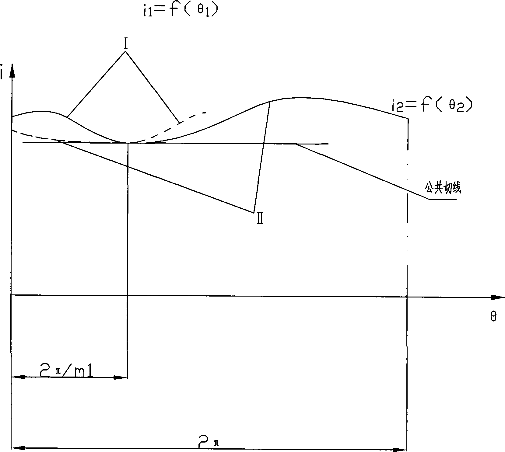
[0003] 1. The transmission ratio curve of ordinary elliptical gears is symmetrically distributed, which easily makes the speed of the separation head different from the speed of the paper feeding wheel, and the two will produce unstable paper feeding during paper delivery
[0004] 2. The friction damping and vibration reduction structure is adopted, and the friction plate directly contacts with the box body for damping and vibration reduction. When the friction force does work, the heat is directly transferred to the box body, causing the box to heat up, and the lubrication in the bearing is quickly volatilized, causing Bearing pinching, thus damaging the transmission structure

Method used

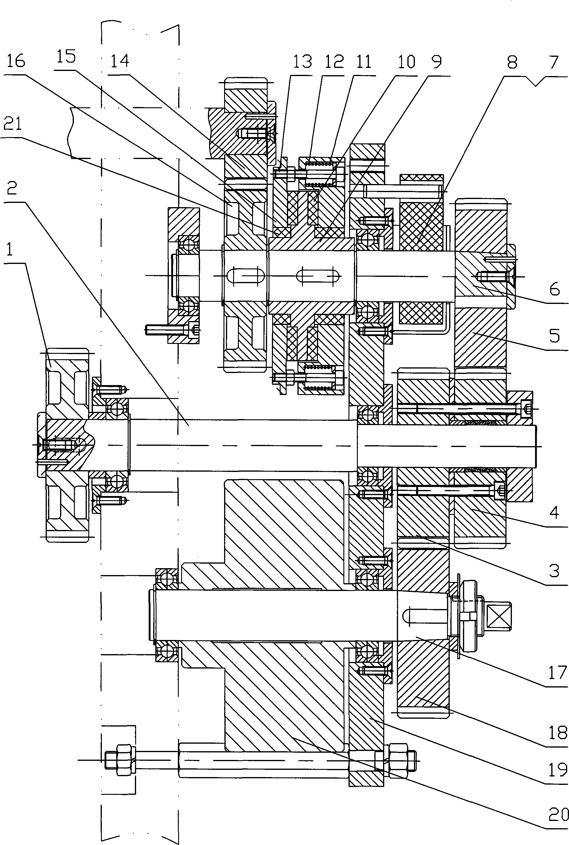

Image

  • Deformed elliptic gear speed change mechanism for paper transport transmission
  • Deformed elliptic gear speed change mechanism for paper transport transmission
  • Deformed elliptic gear speed change mechanism for paper transport transmission

Examples


specific Embodiment approach

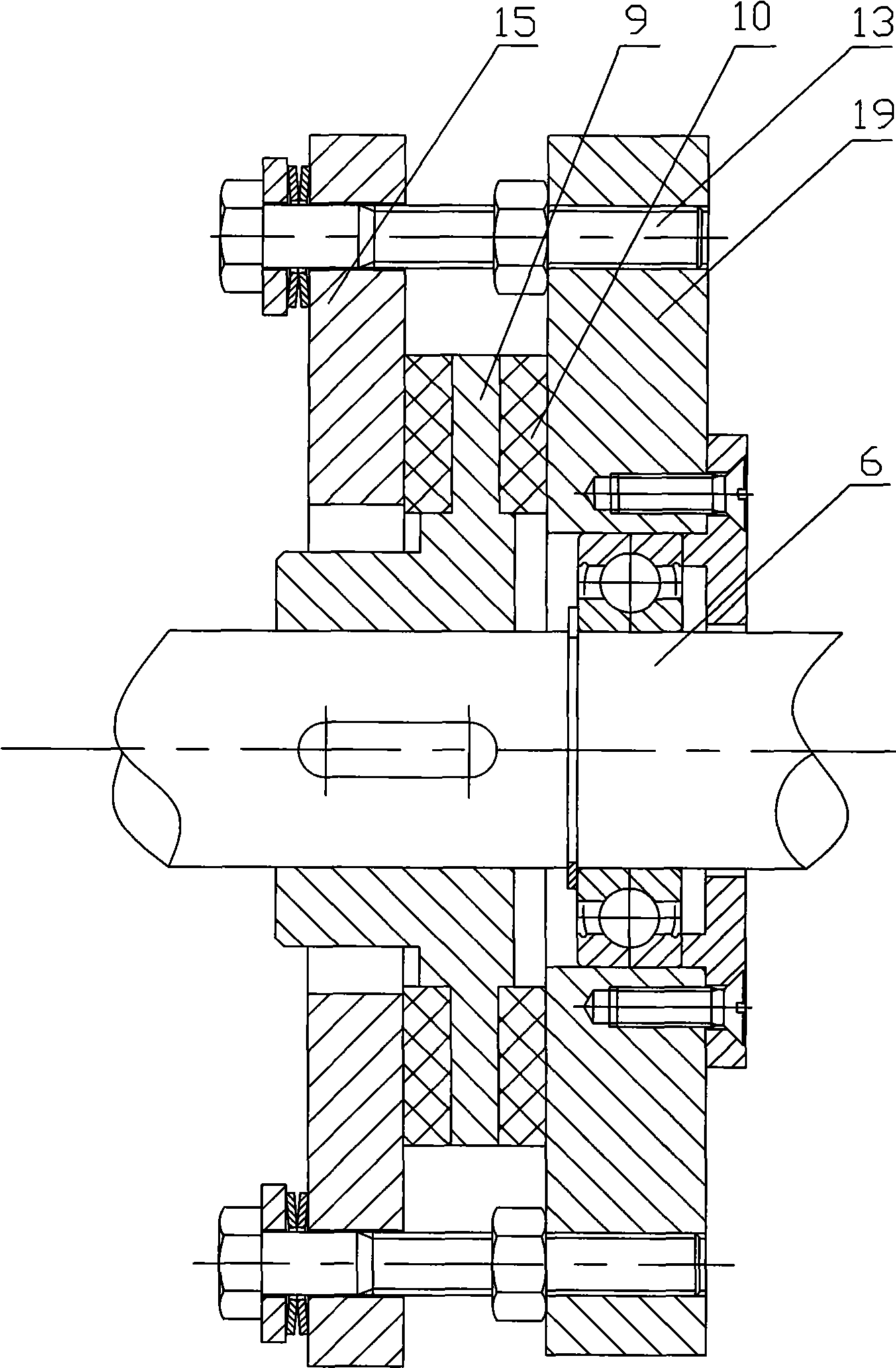
[0028] like figure 2As shown, the input gear 1, the third deformed oval gear 3 and the first deformed oval gear 4 are sequentially installed on the input shaft 2; the inertia flywheel 20 and the fourth deformed oval gear 18 are sequentially installed on the flywheel shaft 17; gear 16, power The damping disc 9, the half-piece damping blocks 7 and 8 arranged on the outer side of the box body 19 and the second deformed oval gear 5 are sequentially installed on the transmission shaft 6, and the sliding bearing 21 and the damping friction plate 10 are installed on the dynamic damping disc 9 and clamped. The disc 15 and the damping flywheel 12 are pressed on the damping friction plate 10 by the spring 11 and the bolt 13; the box 19 and the damping blocks 7 and 8 are provided with a pair of positioning positions that cooperate with each other and make the damping blocks 7 and 8 circumferentially positioned. Pins and positioning holes, damping blocks 7 and 8 are composed of two first...


PUM


Abstract

A deformed oval gear speed-change mechanism for paper feeding transmission relates to a speed-change mechanism of a paper feeder. The speed-change mechanism of a prior paper feeder adopts an oval gear and can cause instability for paper feeding. The deformed oval gear speed-change mechanism comprises a box body, an input shaft and a transmission shaft supported to the box body, a vibration absorber arranged in the middle of the transmission shaft, and a gear cluster arranged between the transmission shaft and the input shaft. The deformed oval gear speed-change mechanism is characterized in that the gear cluster comprises an external gear pair, two engaged gears of the external gear pair are deformed oval gears which are respectively a first deformed oval gear connected to the input shaft and a second deformed oval gear connected to the external end of the transmission shaft, the vibration absorber comprises a power vibration absorber arranged in the box body with a clearance existing between the power vibration absorber and the box body, wherein the power vibration absorber comprises a power damping disc rotating along with the transmission shaft and a damping flywheel sleeved outside the power damping disc, and a damping friction plate is arranged between the damping flywheel and damping disc. The invention ensures accurate paper feeding and stable paper transmission.

Description

【Technical field】 [0001] The invention relates to a speed change mechanism of a paper feeder, in particular to a speed change mechanism using a deformed oval gear. 【Background technique】 [0002] In order to ensure that the high-speed paper feeder can accurately and smoothly position the paper during the high-speed paper feeding process, it is necessary to reduce the speed at which the paper reaches the front gauge and reduce the impact on the front gauge. In the case of no speed change, the paper speed is fast, and the impact on the front gauge is large, resulting in the situation that the thick paper is easy to rebound and the thin paper is easy to deform. Therefore, the high-speed paper feeder must adopt a variable speed paper feeding mechanism. The ordinary elliptical gear speed change mechanism currently used adopts the ordinary elliptical gear set to realize the speed change. This structure has the following disadvantages: [0003] 1. The transmission ratio curve of ...

Claims


Application Information

Patent Timeline
Patent Type & Authority Applications(China)
IPC IPC(8): F16H37/06B41J23/02
Inventor 曹淦初
Owner ZHEJIANG TONGYE PRINTING MACHINERY
Learn More