
Motor shaft

A technology for motor shafts and half shafts, which is applied to shafts, shafts and bearings, mechanical equipment, etc., and can solve the problems of reduced motor power performance and durability

Inactive Publication Date: 2015-02-18
CHANGZHOU NEW SCI METALLURGY MATERIALS
View PDF0 Cites 2 Cited by
  • Summary
  • Abstract
  • Description
  • Claims
  • Application Information

AI Technical Summary

Problems solved by technology

[0003] In view of the above problems, the present invention provides a motor shaft that is convenient for motor assembly and can improve installation efficiency, and can improve the wear resistance of the motor shaft, so as to solve the problem of the gap between the magnetic tile, the rotor cap and the motor shaft after the existing motor is used for a long time. Slight looseness or displacement occurs between the motors, resulting in the reduction of motor power performance and durability

Method used


Image

  • Motor shaft
  • Motor shaft
  • Motor shaft

Examples


Embodiment Construction

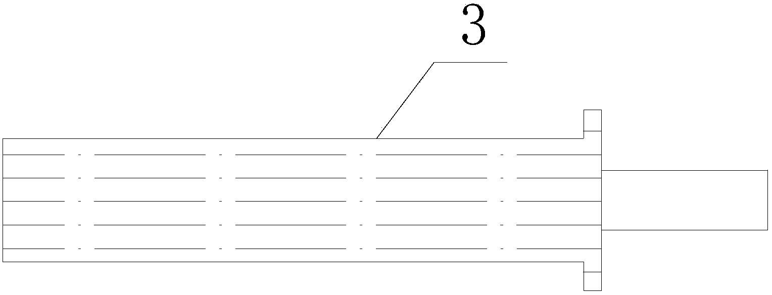
[0014] As shown in the figure, the motor shaft includes a shaft body 1, the shaft body includes a first half shaft 2 and a second half shaft 3, the rear end of the first half shaft 2 is provided with an external thread 4, and the second half shaft 3 The front end is provided with an internal thread corresponding to the external thread 4 at the rear end of the first half shaft 2, and the first half shaft 2 and the second half shaft 3 are connected by internal and external threads. Since the motor shaft body 1 includes the first half shaft The shaft 2 and the second half shaft 3, the first half shaft 2 and the second half shaft 3 are connected by threads, which can facilitate the assembly of the motor and improve the installation efficiency. The front end of the first half shaft 2 is provided with a spring groove 7, and the second half shaft 3 is provided with a limit boss 6, and the bearing can be installed from the other end of the second half shaft 3, which improves the instal...


PUM


Abstract

The invention relates to the technical field of motors, in particular to a motor shaft. The motor shaft comprises a shaft body, and is characterized in that the shaft body comprises a first half shaft and a second half shaft, wherein external threads are formed at the rear end of the first haft shaft; internal threads corresponding to the external threads are formed at the front end of the second half shaft; the first half shaft is connected with the second half shaft through the internal and external threads; knurls and ceramic membranes are arranged on peripheral surfaces of both the first half shaft and the second half shaft. The motor shaft is convenient for motor assembly and can improve the assembly efficiency.

Description

technical field [0001] The invention relates to the technical field of motors, in particular to a motor shaft. Background technique [0002] The motor is used to realize the conversion device of electric energy and mechanical energy and mechanical energy and electric energy. It is the main driving component in the modern industrial system. The rotor of the existing permanent magnet motor is composed of the motor shaft, the magnetic tile and the rotor cap. During the assembly production process, the rotor cap and the magnetic tile need to be fixed with screws, keys or positioning pins, etc., and then the rotor cap is fixed on the motor shaft. The whole process is cumbersome and difficult to improve assembly efficiency. Contents of the invention [0003] In view of the above problems, the present invention provides a motor shaft that is convenient for motor assembly and can improve installation efficiency, and can improve the wear resistance of the motor shaft, so as to solv...

Claims


Application Information

Patent Timeline
IPC IPC(8): F16C3/02
Inventor 邵峰
Owner CHANGZHOU NEW SCI METALLURGY MATERIALS
Learn More