
Backlight module fluorescent tube bracket

A technology of backlight module and lamp tube, which is applied in the directions of optics, light source fixing, nonlinear optics, etc. It can solve the problem that the clamping force and clamping distance are not easy to adjust and control, break, the lamp tube must be snapped and fixed, and the lamp is easily deformed. Tubes and other issues, to achieve simple structure, prevent offset and sliding, good comfort effect

Active Publication Date: 2015-02-18
ANHUI SHILIN LIGHTING
View PDF9 Cites 14 Cited by
  • Summary
  • Abstract
  • Description
  • Claims
  • Application Information

AI Technical Summary

Problems solved by technology

For example, household televisions, monitors of personal computers and laptop computers, mobile phones, and digital cameras are all products that use liquid crystal display devices in large quantities. The backlight module used in liquid crystal display devices is used to supply liquid crystals with sufficient brightness and Evenly distributed light source, so that the liquid crystal display device can display images normally. The backlight module can be divided into edge-light backlight module and direct-light backlight module, each of which is suitable for different sizes of liquid crystal panels. The lamps used in the backlight module include Lamp tubes such as cold cathode fluorescent lamps are easily deformed or broken due to vibration and collision. The lamp tubes must be snapped and fixed to the lamp tube positioning device to cooperate. The application number is CN200810161255.0, which discloses a backlight module lamp The tube bracket includes a base and a lamp tube clamping part. The lamp tube clamping part is set on the base, and a hollow gap is formed on the base on the side of the lamp tube clamping part. The connection between the lamp tube clamping part and the base The area is elastic, allowing the clamping part of the lamp tube to be displaced relative to the base. However, the clamping part of the lamp tube bracket of this kind of backlight module is often integrated, and its clamping force and clamping distance are not easy to adjust and control. When replacing different lamps It is often necessary to re-produce a new matching lamp tube bracket when installing the tube, which is a waste of cost

Method used


Image

  • Backlight module fluorescent tube bracket
  • Backlight module fluorescent tube bracket
  • Backlight module fluorescent tube bracket

Examples


Embodiment Construction

[0015] In order to make the technical means, creative features, goals and effects achieved by the present invention easy to understand, the present invention will be further described below in conjunction with specific embodiments.

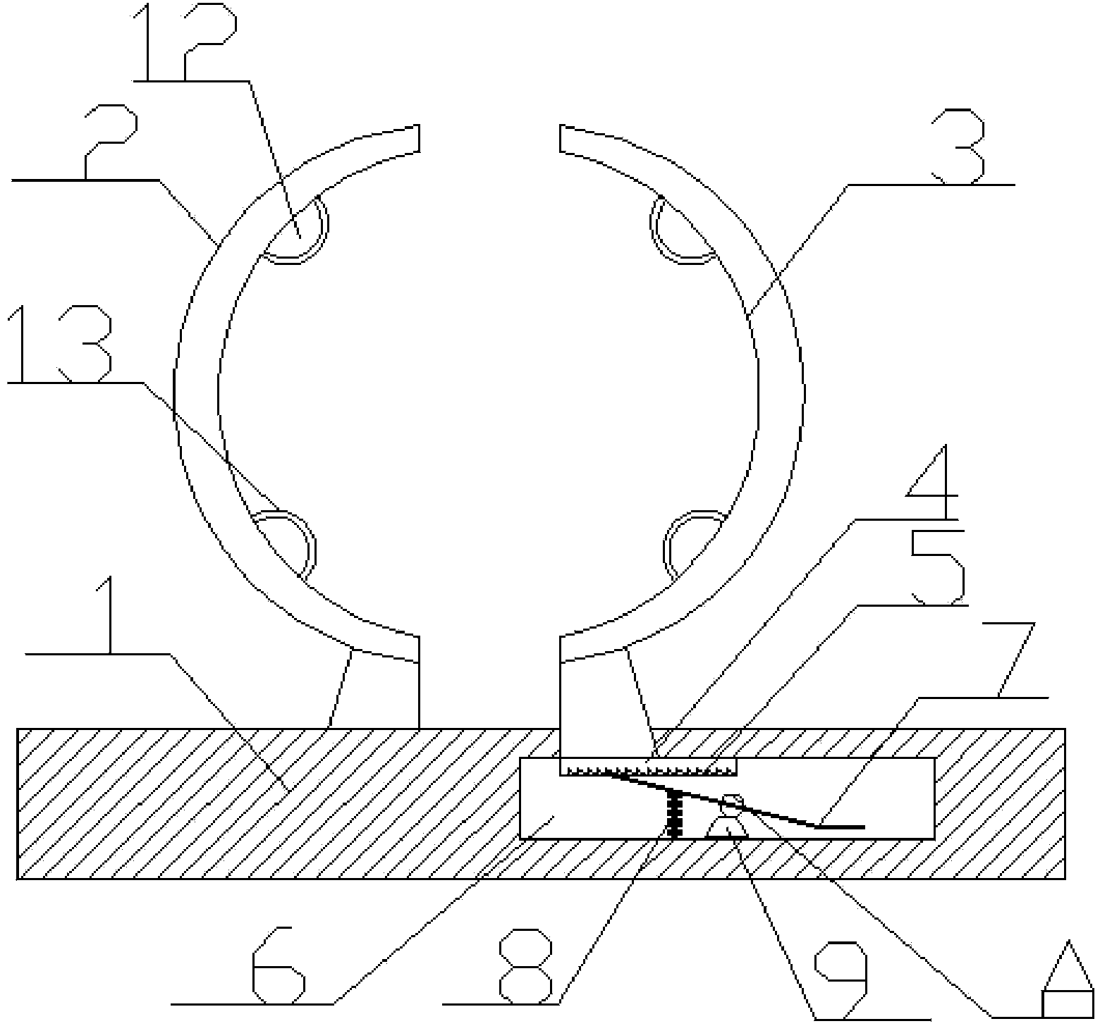
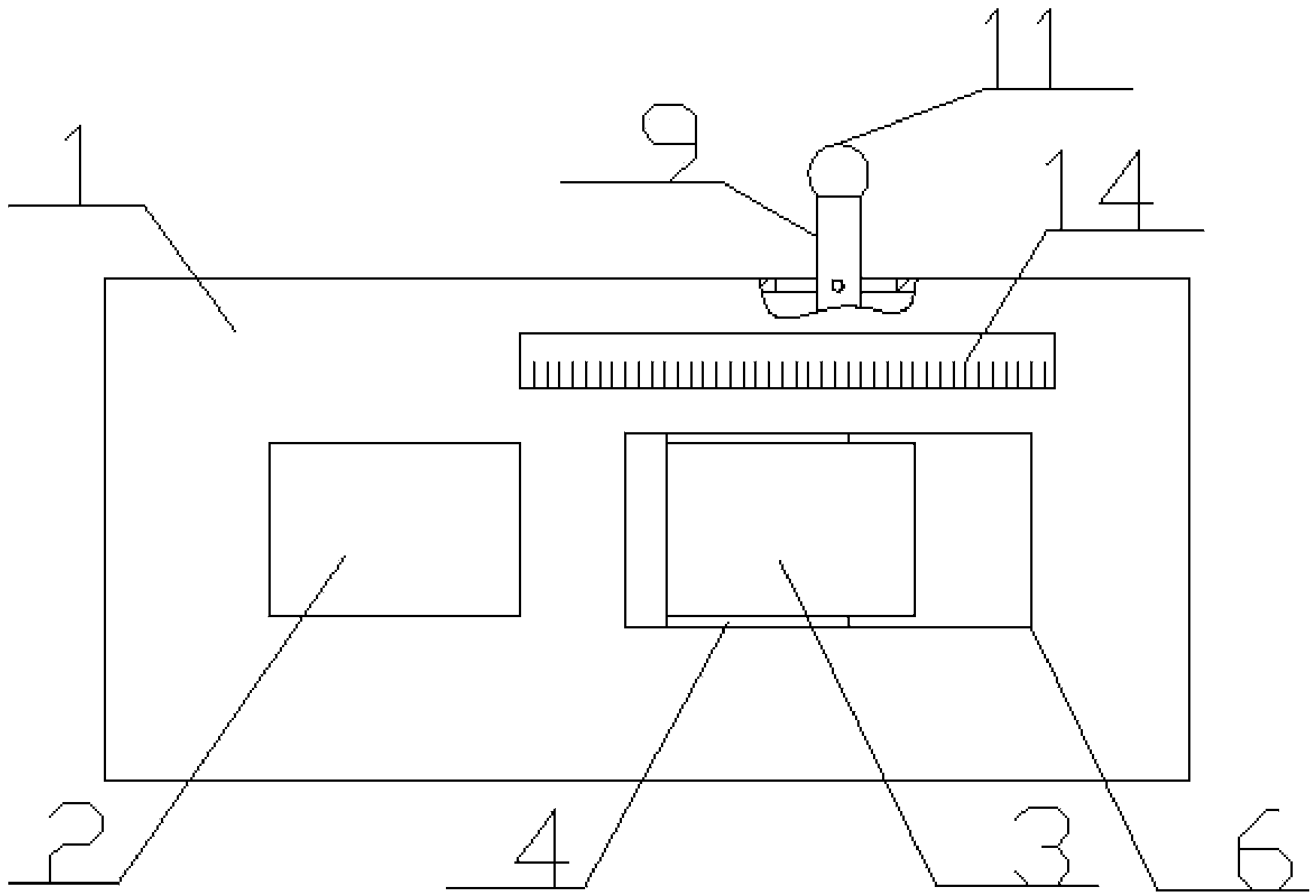
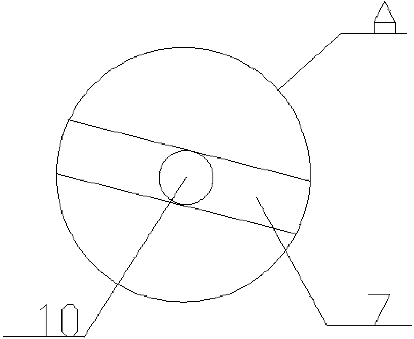
[0016] Such as figure 1 and figure 2 As shown, a lamp tube bracket for a backlight module includes a base 1 and a clamping portion, the clamping portion includes a fixed clamping piece 2 and a movable clamping piece 3, and the bottom of the movable clamping piece 3 is fixedly connected There is a rectangular sliding piece 4, the bottom of the sliding piece 4 is provided with a plurality of equidistant tooth-shaped limit grooves 5, and the base 1 is correspondingly provided with a chute 6, and the sliding piece 4 can be positioned on the chute 6 sliding inside, the chute 6 is provided with a stopper 7, the lower part of one end of the stopper 7 is fixedly connected with a spring 8, and the other end of the spring 8 is clamped at the bottom of the...


PUM


Abstract

The invention discloses a backlight module fluorescent tube bracket and relates to the field of fluorescent tubes. The bracket comprises a base and a clamping part, wherein the clamping part comprises a fixed clamping piece and a movable clamping piece; a rectangular sliding piece is fixedly connected with the bottom of the movable clamping piece; multiple dentation limiting grooves at equal intervals are formed in the bottom of the sliding piece; a sliding groove is correspondingly formed in the base; the sliding piece can slide in the sliding groove; a separation blade is arranged in the sliding groove; a spring is fixedly connected with the lower part of one end of the separation blade; the other end of the spring is connected with the bottom of the sliding groove in a clamping manner; a release link is connected with a side edge shaft of the base and can rotate on the base; one end of the release link is positioned below the separation blade; the other end of the release link extends to the outer side of the base, and the distance between the other end of the release link and the outer side of the base is 2-3 cm; with adoption of the clamping part, the clamping distance can be adjusted as required so as to adjust the clamping force; the backlight module fluorescent tube bracket is convenient and fast to operate, excellent in flexibility, simple in structure, practical and cost-saving.

Description

technical field [0001] The invention relates to the field of lamp tubes, in particular to a lamp tube bracket for a backlight module. Background technique [0002] In recent years, liquid crystal display devices have become the mainstream of various display devices. For example, household televisions, monitors of personal computers and laptop computers, mobile phones, and digital cameras are all products that use liquid crystal display devices in large quantities. The backlight module used in liquid crystal display devices is used to supply liquid crystals with sufficient brightness and Evenly distributed light source, so that the liquid crystal display device can display images normally. The backlight module can be divided into edge-light backlight module and direct-light backlight module, each of which is suitable for different sizes of liquid crystal panels. The lamps used in the backlight module include Lamp tubes such as cold cathode fluorescent lamps are easily deform...

Claims


Application Information

Patent Timeline
Patent Type & Authority Applications(China)
IPC IPC(8): F21V19/00F21V15/04G02F1/13357
CPCF21V15/04F21V19/0015G02F1/133602
Inventor 桑永树李运鹤刘军李建
Owner ANHUI SHILIN LIGHTING
Learn More