Rack-mounted air-conditioner used in cabinet-type data center
A rack-type and cabinet-type technology, which is applied in the field of rack-type air conditioners, can solve the problems of small air-conditioning cooling capacity, large wind side resistance, and increased cabinet size, so as to improve cooling efficiency, reduce energy loss, and shorten air supply effect of distance
- Summary
- Abstract
- Description
- Claims
- Application Information
AI Technical Summary
Problems solved by technology
Method used
Image

Examples
Embodiment Construction
[0022] The present invention provides a rack-type air conditioner for a rack-type data center. In order to make the purpose, technical solution and effect of the present invention more clear and definite, the present invention will be further described in detail below with reference to the accompanying drawings and examples. It should be understood that the specific embodiments described here are only used to explain the present invention, not to limit the present invention.
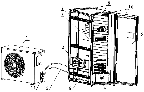
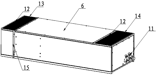
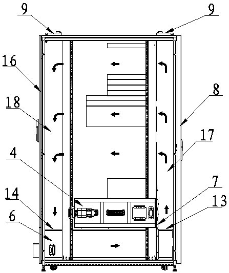
[0023] In order to solve the problems existing in the existing technology, please refer to figure 1 As shown, a rack-mounted air conditioner for a rack-type data center includes an outdoor unit 1 for cooling, an indoor unit 10 connected to the outdoor unit 1 for placing electrical equipment and providing cooling air for the electrical equipment, The indoor unit 10 is provided with an air supply device 6 for circulating air supply to the electrical equipment.
[0024] In the present invention, the outdoo...
PUM
 Abstract
Description
Claims
Application Information
PatSnap Eureka turns technology decisions into work you can execute. Powered by our Innovation Knowledge Graph, it runs expert workflows across engineering, life sciences, materials and intellectual property. Get your review-ready output in minutes.


