Lens combination structure and machine vision lens with the structure

A combined structure and lens technology, applied in the field of optical mirrors, can solve the problems of less than 5 million pixels and cannot meet the needs of high-end products, and achieve the effect of meeting the needs of high-end products

Active Publication Date: 2016-08-24
GUANGDONG AOPUTE TECH CO LTD
View PDF5 Cites 0 Cited by
  • Summary
  • Abstract
  • Description
  • Claims
  • Application Information

AI Technical Summary

Problems solved by technology

For the existing domestic machine vision lens with a focal length of 25mm, when the chip size is 2 / 3", the number of pixels cannot reach 5 million, which cannot meet the needs of high-end products.

Method used


Image

  • Lens combination structure and machine vision lens with the structure
  • Lens combination structure and machine vision lens with the structure
  • Lens combination structure and machine vision lens with the structure

Examples


Embodiment Construction

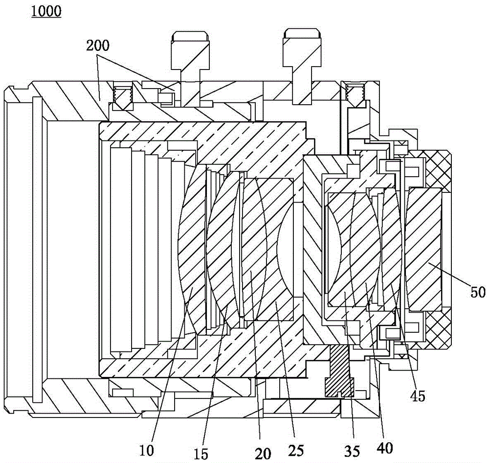
[0025] refer to Figure 1 to Figure 10 , the machine vision lens 1000 of the present invention includes a lens barrel 200 and a lens combination structure 100 , and the lens combination structure 100 is installed in the lens barrel 200 .

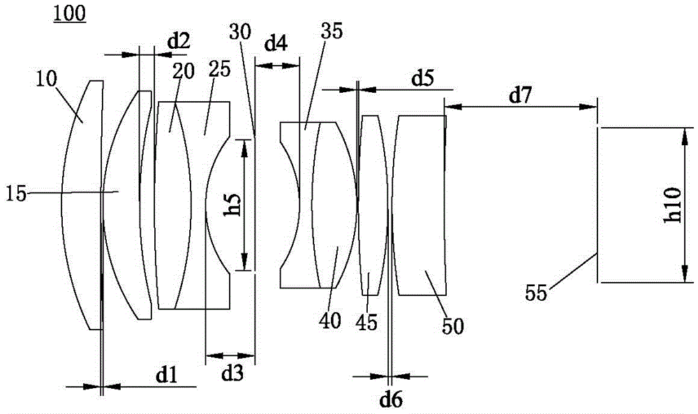
[0026] Wherein, the lens combination structure 100 includes a first lens 10, a second lens 15, a third lens 20, a fourth lens 25, a diaphragm 30, a fifth lens 35, a sixth lens 40, a seventh lens whose central axes are located on the same horizontal line. The lens 45 and the eighth lens 50 .

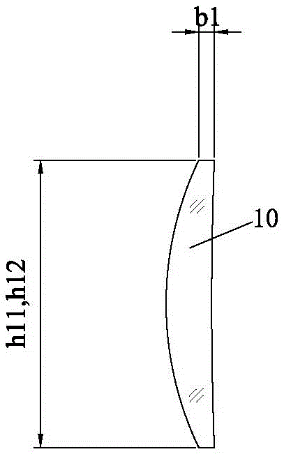
[0027]The front end surface of the first lens 10 is a convex surface with a radius of 20.832 ± 0.1 millimeters, the side wall thickness b1 of the first lens 10 is 0.96 ± 0.1 millimeters, the height h11 of the front end surface of the first lens 10 and the height h12 of the rear end surface are both 18 ± 0.1 mm, the rear end surface of the first lens 10 is a concave surface with a radius of 255.31 ± 0.1 mm; the front end surface of the second lens 15 is...


PUM


Abstract

The invention relates to the technical field of optical lenses and particularly relates to a lens combined structure. The lens combined structure comprises a first lens, a second lens, a third lens, a fourth lens, a diaphragm, a fifth lens, a sixth lens, a seventh lens and an eighth lens, center axes of which are positioned on the horizontal line, wherein the distance between the top of the front end surface of the eighth lens and the top of the rear end surface of the seventh lens is regulated between 0.1mm and 6mm. When the focal length is 25mm by virtue of the lens combined structure, the dimension of the corresponding chip is 2 / 3'', the pixel value of the lens combined structure can reach 5 millions of pixels, so that the high-end product needs are met, and the clear aperture of the lens combined structure can be flexibly regulated. Besides, the invention further discloses a machine visual lens with the lens combined structure.

Description

technical field [0001] The invention relates to the technical field of optical mirrors, in particular to a lens combination structure and a machine vision lens with the structure. Background technique [0002] Machine vision is the use of machines instead of human eyes for measurement and judgment. The machine vision system refers to converting the ingested target into an image signal through a machine vision product (that is, an image capture device, which is divided into two types: CMOS and CCD), and sending it to a dedicated image processing system. The image system performs various calculations on these signals to extract the characteristics of the target, and then controls the on-site equipment actions according to the results of the discrimination. [0003] In recent years, with the rapid development of the microelectronics industry, machine vision systems with high resolution and high processing speed have been born continuously, which puts forward new requirements f...

Claims


Application Information

Patent Timeline
Patent Type & Authority Patents(China)
IPC IPC(8): G02B13/00
CPCG02B13/00
Inventor 卢盛林赵有名
Owner GUANGDONG AOPUTE TECH CO LTD
Why Eureka
Try Eureka