
Spliced screen display device and displaying driving method thereof

A display device and display drive technology, applied to static indicators, instruments, etc., can solve problems such as imperfect heat dissipation and insufficient accommodation for drives

Active Publication Date: 2015-02-18
GUANGDONG VTRON TECH CO LTD
View PDF7 Cites 1 Cited by
  • Summary
  • Abstract
  • Description
  • Claims
  • Application Information

AI Technical Summary

Problems solved by technology

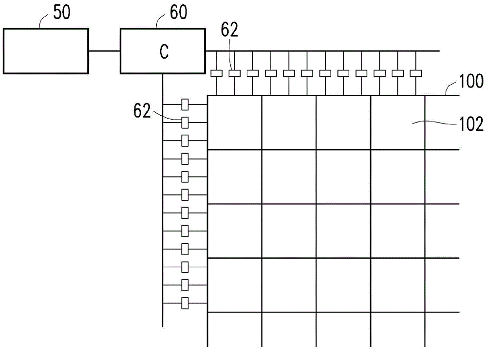
[0008] The embodiment of the present invention provides a splicing screen display device and its display driving method, which solves the technical problem that a sub-screen requires more drivers to be set up in the existing traditional splicing screen, and at the same time, avoids The available area behind the secondary screen will cause technical problems of not being able to accommodate these drivers enough, and the technical problems of insufficient heat dissipation

Method used


Image

  • Spliced screen display device and displaying driving method thereof
  • Spliced screen display device and displaying driving method thereof
  • Spliced screen display device and displaying driving method thereof

Examples


no. 1 example

[0067] see Figure 4 , the first embodiment of a splicing screen display device provided in the embodiment of the present invention includes:

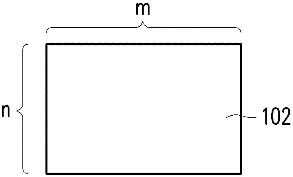
[0068] Because the image resolution of the current flat display panel is much larger than the image resolution of a sub-screen 102 . A common flat panel display is, for example, a liquid crystal display panel (LCD panel) or a light emitting device display panel (LED panel), and its image resolution is, for example, 720x480, 1920x1080 or even higher image resolution. Therefore, the driver used in the flat display panel, such as the single data driver 220 , has a number of driving channels that is greater than the number of channels required by one sub-screen in the splicing screen 100 . Therefore, for a sub-screen of the present invention, for example, only one data driver is required, or in response to the development of higher image resolution, only a small number of data drivers can be used to drive a sub-screen. Since the driving ...

no. 2 example

[0078] see Figure 7 , a second embodiment of a display driving method provided in an embodiment of the present invention includes:

[0079] Figure 7 Shown is another variant embodiment, but the mechanism is still the same as Image 6 The illustrated embodiments are similar, with the following differences:

[0080] In the present invention Figure 7 In the illustrated embodiment, each secondary screen is provided with a corresponding frame memory, and the capacity of the frame memory only needs to be able to store images of the secondary screen. compared to Image 6 example of the Figure 7 Step S250 and step S252 are interchanged.

[0081] It must be noted that in step S252, the input image to be displayed is allocated before it is stored in the frame memory, and then the allocated sub-frame data is stored in the corresponding sub-frame in step S250 in memory. Then step S254 and step S256 are the same as Image 6 .

[0082] The following describes the correction mech...


PUM


Abstract

The invention discloses a spliced screen display device and a displaying driving method thereof, solving the technical problems that the existing traditional spliced screen causes the situation that one screen needs more drivers, and drivers cannot be contained in the usable area except for the area behind the second screens as well as the technical problem that the heat dissipation is incomplete. The spliced screen display device comprises a display screen, a plurality of data drivers and a picture frame rate control circuit, wherein the display screen is formed by splicing a plurality of secondary screens; the plurality of data drivers are used for respectively driving the plurality of secondary screens; the picture frame rate control circuit is used for increasing the original picture frame rate by K times according to the original picture frame rate receiving images, so as to generate K picture frames for the plurality of data drivers within one picture period corresponding to the original picture frame rate.

Description

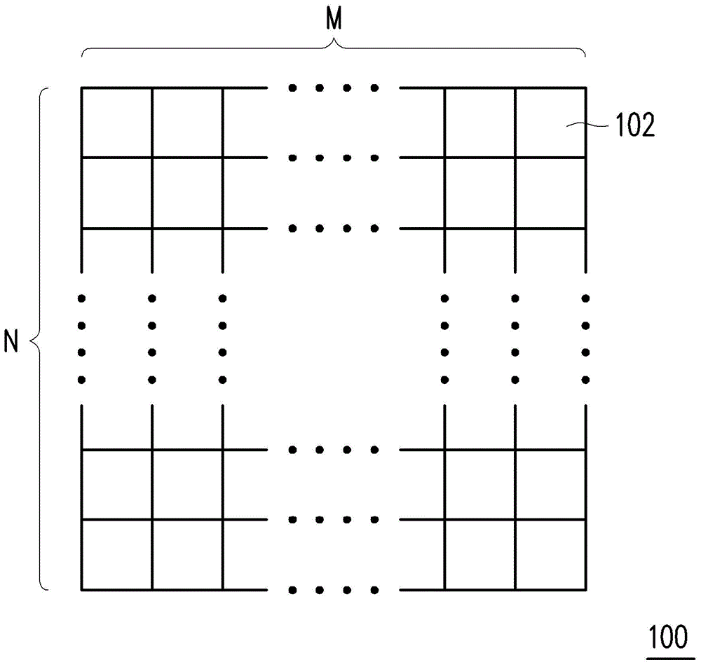
technical field [0001] The invention relates to the technical field of driving a splicing screen display device, in particular to a splicing screen display device and a display driving method thereof. Background technique [0002] For a large display area, such as a digital advertising billboard, or an indoor TV wall, etc., since the display area is much larger than that of a single display device, a splicing screen display device is used to display images. [0003] The so-called tile display device has a plurality of sub-screens (tile screens) respectively displaying a part of an image, and these sub-screens are spliced ​​to form a large-sized display screen. figure 1 It is a schematic diagram of the structure of a traditional splicing screen. Such as figure 1 As shown, the large-sized splicing screen 100 is formed by splicing a plurality of small-sized sub-screens 102 in an M×N matrix. Therefore, the value of M is usually greater than the value of N, but it can also be ...

Claims


Application Information

Patent Timeline
Patent Type & Authority Applications(China)
IPC IPC(8): G09G3/32
Inventor 许景翔
Owner GUANGDONG VTRON TECH CO LTD
Learn More