
LED device packaging method with metal substrate

A technology of LED devices and metal substrates, which is applied in semiconductor devices, electrical components, circuits, etc., can solve the problems of deformation of metal substrates, residual glue on metal substrates, etc., and achieve the effects of improving quality, simple process implementation, and avoiding the possibility of damage

Active Publication Date: 2017-02-22
FUJIAN TIANDIAN OPTOELECTRONICS CO LTD
View PDF3 Cites 1 Cited by
  • Summary
  • Abstract
  • Description
  • Claims
  • Application Information

AI Technical Summary

Problems solved by technology

[0004] The technical problem to be solved by the present invention is to provide a LED device packaging method with a metal substrate, which is used to solve the problem of deformation of the hollow metal substrate during the packaging process and the problem of residual glue on the back and hollow of the metal substrate

Method used


Image

  • LED device packaging method with metal substrate
  • LED device packaging method with metal substrate
  • LED device packaging method with metal substrate

Examples


Embodiment Construction

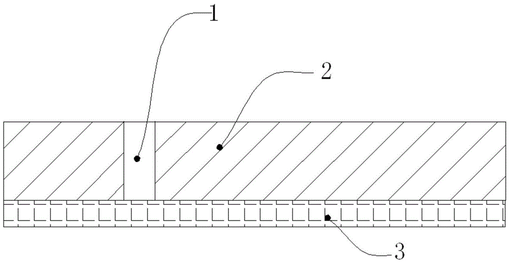
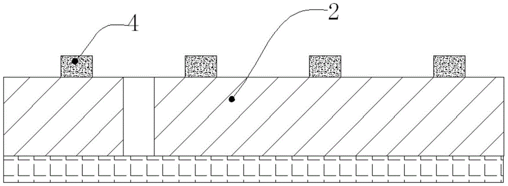
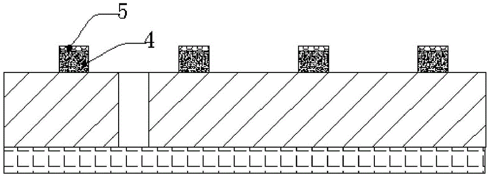
[0041] The present invention provides a method for packaging an LED device with a metal substrate. The metal substrate is a hollow substrate, including: pasting a film, pasting a layer of pasting film on the back of the metal substrate; die bonding, fixing the LED chip on the metal substrate and die bonding Line forming circuit; making fluorescent layer, making fluorescent layer on LED chip; packaging, making encapsulation layer on LED chip to encapsulate LED chip; removing film, removing the film; slicing, cutting the metal substrate to make each The LED chip forms an independent unit.

[0042] The present invention will be further described in detail below with reference to the drawings and specific embodiments.

[0043] For the first embodiment of the LED device packaging method with a metal substrate of the present invention, see Figure 1 to Figure 6 Shown.

[0044] The metal substrate 2 is a silver-plated copper sheet, which is a hollow substrate. The hollow includes various ...


PUM


Abstract

The invention discloses a method for encapsulating an LED device with a metal substrate. The method is used for solving the problems that a hollowed-out metal substrate deforms in the encapsulating process, and residual glue exists on the back face and the hollowed-out parts of the metal substrate. The method for encapsulating the LED device comprises the steps of film attaching, wherein an attaching film is attached to the back face of the hollowed-out metal substrate; conducting solid phase crystallization, wherein LED chips are fixed to the metal substrate, and solid phase crystallization is conducted on weld lines to form circuits; manufacturing fluorescent layers, wherein the fluorescent layers are manufactured on the LED chips; conducting encapsulating, wherein encapsulating layers are manufactured on the LED chips, and the LED chips are encapsulated; film removing, wherein the attaching film is removed; conducting slicing, wherein the metal substrate is cut, and each LED chip forms an independent unit. By means of the technology, glue cannot remain on the back of the metal substrate, the phenomenon of loose contact can be avoided, and the additional process for removing the residual glue is not needed.

Description

Technical field [0001] The invention relates to a packaging technology of LED devices. Background technique [0002] The prior art mainly uses thermosetting materials and silver-plated copper sheets as substrates, and uses thermosetting materials to form a cup to form a support. In the cup, a die is bonded and coated with fluorescent glue to form an LED device. [0003] If the thermosetting bowl is not made, due to the ductility of the metal substrate, uncontrollable deformation of the metal substrate may occur when bonding wires on the metal substrate, resulting in unqualified products. In addition, the LED chip needs to be packaged on the metal substrate. In the existing hollow metal substrate, when packaging, the packaging glue will flow into the back of the metal substrate along the hollow gap or hole, forming a bump, which will cause the substrate Poor contact when soldering to the circuit board. In order to avoid the problem of protrusions in the hollows, the existing metho...

Claims


Application Information

Patent Timeline
Patent Type & Authority Patents(China)
IPC IPC(8): H01L33/56H01L33/00
CPCH01L33/005H01L33/56H01L2933/005
Inventor 庄蕾蕾张月强
Owner FUJIAN TIANDIAN OPTOELECTRONICS CO LTD
Learn More