Transit system for 10 kV switch trolley

A technology of switching trolleys and transfer vehicles, which is applied in the field of switch cabinets, can solve the problems of automatic push and pull of transfer vehicles, and achieve the effects of saving manpower, improving safety and reliability, and reducing personnel operations

Active Publication Date: 2015-02-18
STATE GRID CORP OF CHINA +1
View PDF11 Cites 5 Cited by
  • Summary
  • Abstract
  • Description
  • Claims
  • Application Information

AI Technical Summary

Problems solved by technology

[0006] The structure of the transfer vehicle of the above-mentioned patents is relatively simple, which cannot solve the technical problem of automatic push and pull of the transfer vehicle

Method used


Image

  • Transit system for 10 kV switch trolley
  • Transit system for 10 kV switch trolley
  • Transit system for 10 kV switch trolley

Examples


Embodiment Construction

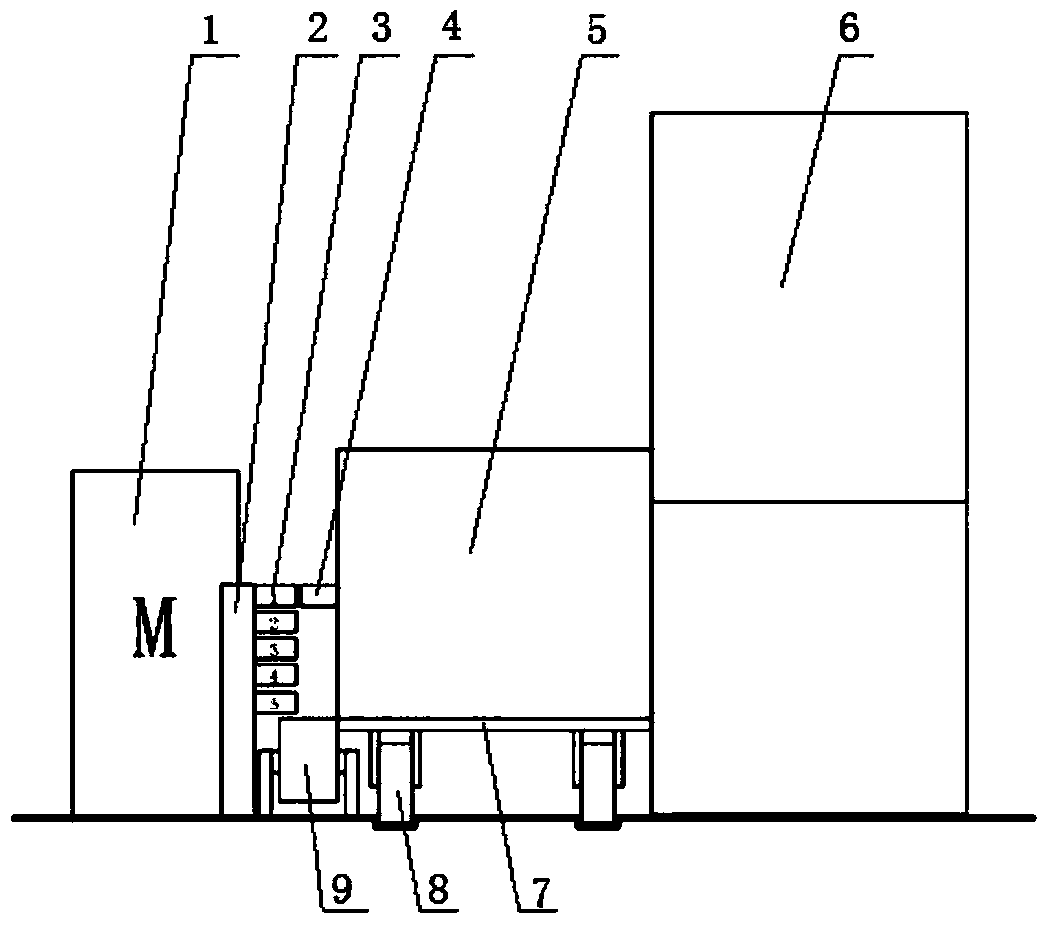
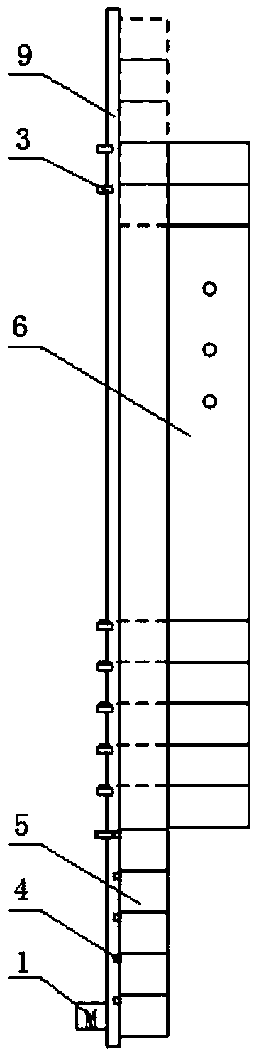
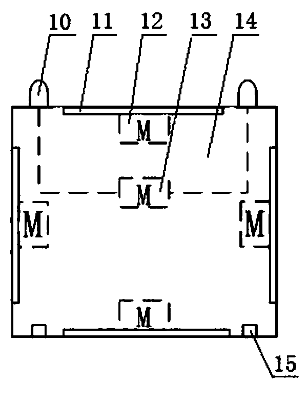
[0032] The present invention will be further described in detail below in conjunction with the accompanying drawings and through specific embodiments. The following embodiments are only descriptive, not restrictive, and cannot limit the protection scope of the present invention.

[0033] A transfer system for 10kV switch trolleys, including a transfer vehicle 5, a transfer vehicle conveyor belt 9, a positioning rod 2, and a transfer vehicle proximity switch 3, and the transfer vehicle conveyor belt is installed in parallel on the door side of the switch cabinet 6 and the switch cabinet at a certain distance , multiple transfer vehicles are slidably installed on the transfer vehicle conveyor belt between the transfer vehicle conveyor belt and the switch cabinet, and a positioning rod is installed on the outside of the transfer vehicle conveyor belt corresponding to the cabinet door of each switch cabinet, and each positioning rod is up And a plurality of transfer vehicle proximi...


PUM


Abstract

The invention relates to a transit system for a 10kV switch trolley. The transit system comprises a plurality of transit trolleys, a transit trolley conveying belt, positioning rods and transit trolley proximity switches. The transit trolley conveying belt is parallelly arranged on one side of a door of a switch cabinet and not abutted against the switch cabinet. The transit trolleys are slidably arranged on a portion, between the transit trolley conveying belt and the switch cabinet, of the transit trolley conveying belt. The positioning rods are mounted on the outside of the transit trolley conveying belt and correspond to the doors of the switch cabinets. Multiple of the transit trolley proximity switches are mounted on each positioning rod from the top down. Positioning blocks are arranged on the transit trolleys used for positioning detection of the transit trolley proximity switches on the positioning rods. The transit system has the advantages that a PLC (programmable logic controller)-controlled high-power translation portal crane and a push-rod motor are adopted; though a touch screen, the user operates and selects the transit trolley and action commands, and desired effects such that manual operation is reduced, automatic control is achieved and safety and reliability are improved are realized.

Description

technical field [0001] The invention belongs to the field of switch cabinets and relates to a switch trolley, in particular to a transfer system for a 10kV switch trolley. Background technique [0002] During the daily switch cabinet maintenance experiment, it is necessary to push the transfer car to the front of the switch cabinet, then open the switch cabinet door, drag the switch trolley to the transfer trolley, and the switch trolley is in the process of being inspected and sent back to the switch cabinet They are all manually pushed and pulled in place. Since the switch trolley and the transfer vehicle are relatively heavy in weight, it consumes a lot of physical strength of the workers, the transportation time is long, and the work efficiency is low. Moreover, the switch trolley is easy to topple over in the process of being transported to the maintenance position on the transfer vehicle, which poses a threat to the safety of the equipment. [0003] By searching, the ...

Claims


Application Information

Patent Timeline
Patent Type & Authority Applications(China)
IPC IPC(8): H02B3/00
CPCH02B3/00
Inventor 王一品李延生吴胜志王兴国刘彦婧杨晓坤
Owner STATE GRID CORP OF CHINA
Why Eureka
Try Eureka