Post structure

A pillar structure and pillar technology, applied in the direction of connecting components, detachable tables, furniture connections, etc., can solve problems such as layout changes, and achieve the effects of preventing snapping, preventing loosening, and simple loading and unloading operations.

Inactive Publication Date: 2015-02-18
KYOSHIN SANGYO
View PDF6 Cites 7 Cited by
  • Summary
  • Abstract
  • Description
  • Claims
  • Application Information

AI Technical Summary

Problems solved by technology

In addition, the display is not fixed throughout the year. For example, special stores are opened every season, every month or every week, which changes the layout of the store.

Method used


Image

  • Post structure
  • Post structure
  • Post structure

Examples


Embodiment 2

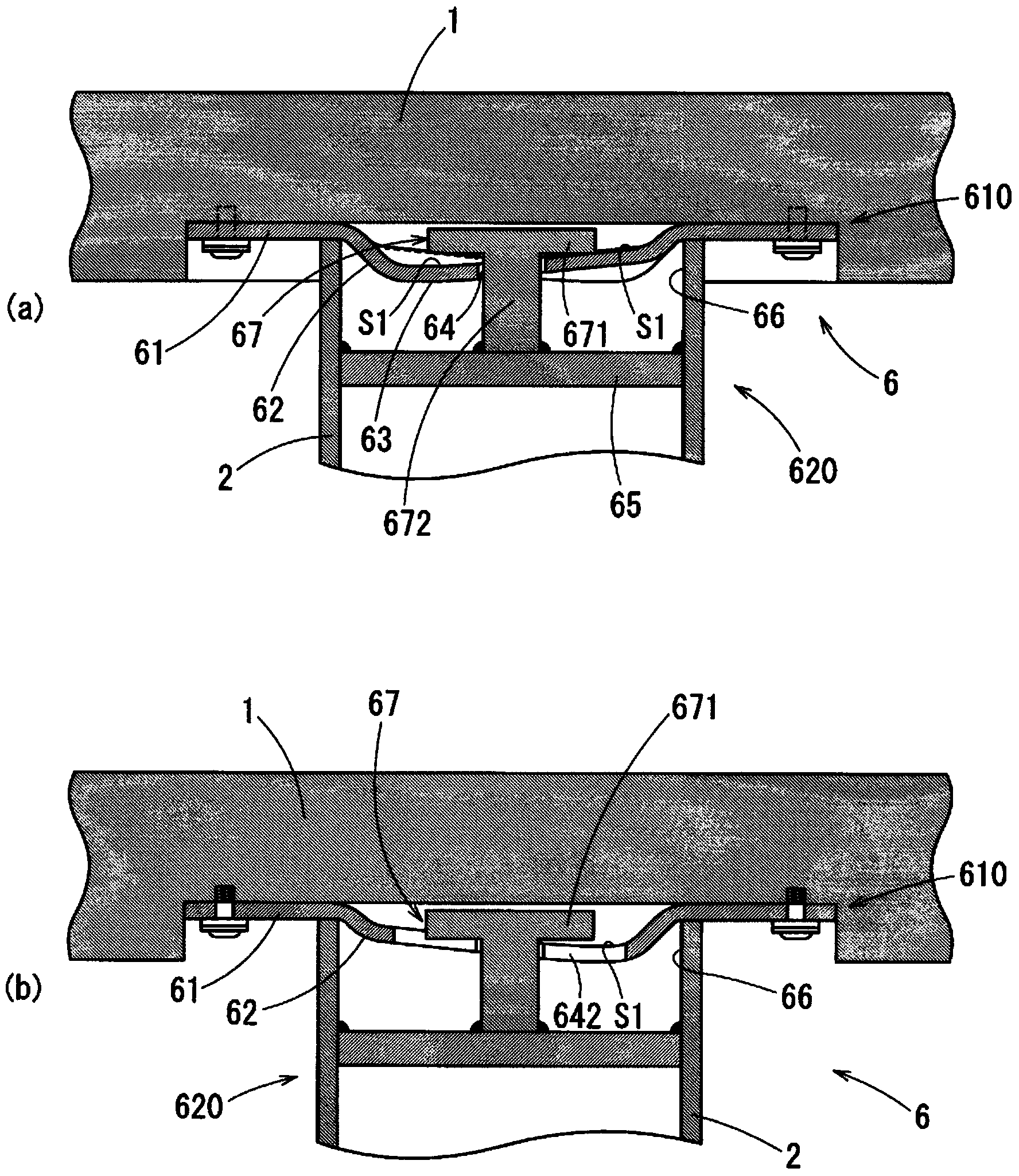
[0083] Refer below Figure 5 , 6 illustrates Embodiment 2 of the present invention. Figure 5 It is a sectional view showing the fixing metal fitting of Example 2. Image 6 It is a sectional view showing the disassembled same fixing metal fittings. The main difference between the second embodiment and the first embodiment is the structure of the fixing part 610 of the fixing metal part 6 .

[0084] Such as Figure 5 Figure (a) and Image 6 As shown, the fixing part 610 of the second embodiment fits the second base 71 concave upwards and the first base 61 concave downwards in such a way that the respective concave parts are opposite to each other, so that it can be closed like a shell cover. state composition. That is, the second base 71 above is stabilized in the recess of the top plate 1, and the first base 61 is screwed on the top plate 1 from below in a manner facing the second base 71, and a gap is formed between the facing recesses. Hollow 80. The cavity 80 accommo...

Embodiment 3

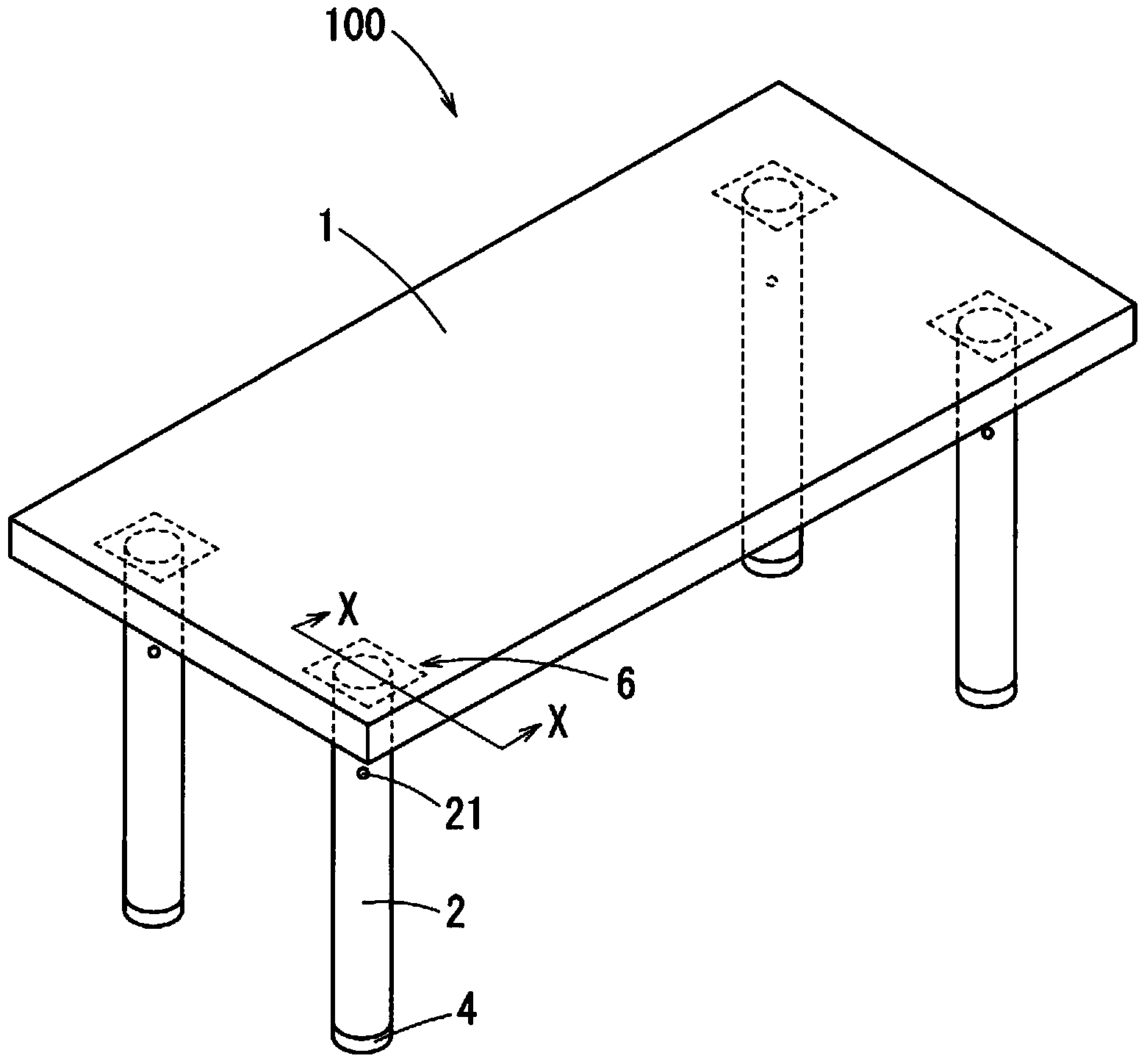
[0091] Below, refer to Figure 8 , 9 Embodiment 3 of the present invention will be described. Figure 8 It is a perspective view of the desk of Example 3, Figure 9 The (a) figure is the inner surface view of the top plate, and the (b) figure in the same figure is the top view of the bottom plate. The main difference between Embodiment 3 and Embodiments 1 and 2 is that the upper end of the pillar 2 uses the fixing metal piece 6 to fix the top plate 1 , on the other hand, the lower end of the pillar 2 uses the fixing metal piece 6 to fix the bottom plate 3 .

[0092] Such as Figure 8 As shown, the table 200 of embodiment 3 uses the same fixing metal piece 6 as in embodiment 1 or embodiment 2 to fix the top plate 1 at the upper end of the pillar 2 and fix the bottom plate 3 at the lower end. In addition, since it can be quickly disassembled and disassembled into three parts of the top plate 1, the pillar 2, and the bottom plate 3 after use, it is convenient for transportat...

Embodiment 4

[0094] Below, refer to Figure 10 Embodiment 4 of the present invention will be described. Figure 10 It is a perspective view of the display rack of Example 4. The main difference between Embodiment 4 and Embodiments 1 to 3 is that the pillar 2 is fixed on the bottom plate 3 by using the fixing metal piece 6 .

[0095] Such as Figure 10 As shown, the display rack 300 of Embodiment 4 has left and right pillars 2, 2, using the same fixing metal parts as in Embodiment 1 and Embodiment 2, the lower ends of the pillars 2, 2 are respectively fixed on the Bottom plate 3. That is, the (first) base 61 of the fixing metal part 6 is fixed on the base plate 3 by screw connection etc., and the lower end of the pillar 2 is fixed on the ( First) on the base 61. In addition, a display rack 300 is formed by erecting shelves 5 in multiple layers on the left and right pillars 2 , 2 through a plurality of cutouts 22 in the axial direction (up and down directions). In the display rack 300 ...


PUM


Abstract

[Problem] To design for convenient storage / transport of a table, display case, etc. when not in use by quick removal of posts from the tabletop and / or base plate thereof. [Solution] A post structure in which a rotationally moving part is fitted into a stationary part wherein: a base configuring the stationary part is fastened to the table top and / or base plate, a short cylindrical interlocking projection juts out from the base, an insertion hole is drilled in the bottom face of the interlocking projection and helical surfaces that each slope gently are formed on both sides of the insertion hole; meanwhile, the moving part is fixed on the end of the post, a cross plate is made to bridge the post in the diameter direction almost at the end thereof, and a T-shaped locking rod is provided to stand substantially at the center of the cross plate; and by inserting the interlocking projection of the stationary part into the inner circumference of the post of the rotationally moving part while inserting the fastening rod of the T-shaped locking rod in the insertion hole of the bottom face and turning the post around the axis, the fastening rod is tightened onto the helical surface while the rotationally moving part is fastened to the stationary part. Grooves are provided on the helical surface at equal angular intervals in a radiating pattern.

Description

technical field [0001] The present invention relates to a pillar structure of furniture such as a table or a display rack. When the pillars are vertically provided on the top plate and / or the bottom plate, a locking mechanism is provided to allow the pillars to be attached and detached by one-touch operation. The details of the support structure are to prevent the support from being excessively fastened to the top plate and / or the bottom plate when installing furniture such as desks or display racks, and it is difficult to detach even if it is subject to sudden impact or vibration. The struts can be quickly disassembled from the top and / or bottom panels when not in use. Background technique [0002] Known in the prior art, a kind of table that has freely removable legs or pillars, and adopts, uses bolt, nut to be installed on the inside method that the seat plate that is installed on the upper end of leg is freely removable. In addition, if it is a low table, etc., implemen...

Claims


Application Information

Patent Timeline
Patent Type & Authority Applications(China)
IPC IPC(8): F16B12/52A47B3/06
CPCA47B2013/022A47B13/021
Inventor 长屋敏彦长屋光彦
Owner KYOSHIN SANGYO
Why Eureka
Try Eureka