U-shaped bending die with shaping function

A bending mold, U-shaped technology, applied in the field of bending molds, can solve the problems of poor U-shaped parts, cumbersome operation, complex structure, etc.

Inactive Publication Date: 2015-02-25
CHANGZHOU YONGAN SECURITY SERVICE
View PDF0 Cites 12 Cited by
  • Summary
  • Abstract
  • Description
  • Claims
  • Application Information

AI Technical Summary

Problems solved by technology

[0002] In the ever-growing modern industry, automobiles, electrical appliances and other industries, the demand for parts of various shapes is increasing, including U-shaped parts. Most of the exis

Method used


Image

  • U-shaped bending die with shaping function
  • U-shaped bending die with shaping function

Examples


Embodiment Construction

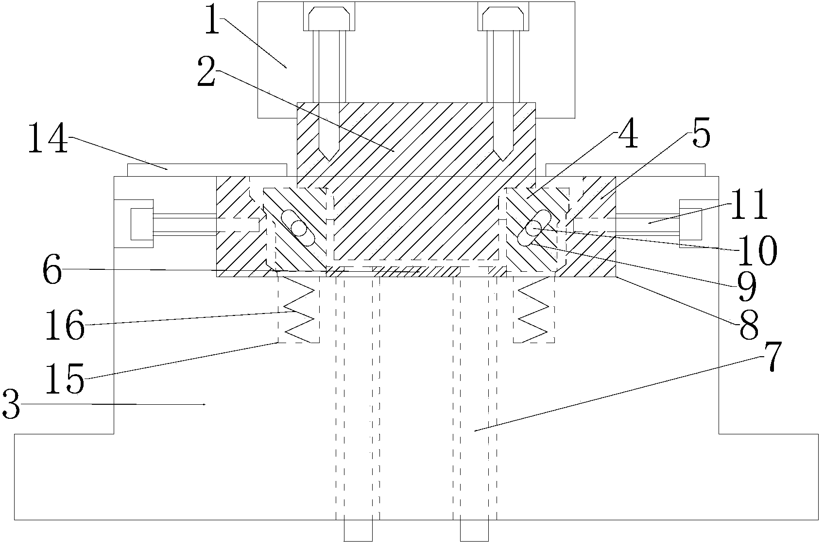
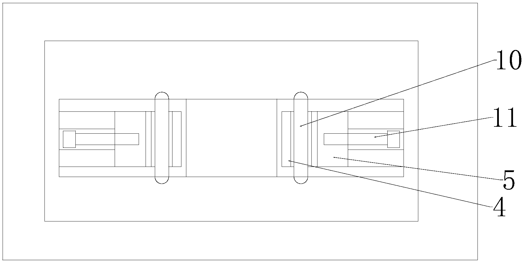
[0013] Depend on figure 1 and figure 2 It can be seen that the U-shaped bending die with shaping of the present invention comprises an upper mold base 1, a punch 2, a lower mold base 3, a die 4, a wedge 5, a top plate 6 and a guide rod 7, and the punch 2 communicates with the upper mold base. 1 is fixedly connected by screws, the lower mold base 3 is provided with a working groove 8, and the working groove 8 is provided with two symmetrical dies 4 and two wedges 5, and the wedges 5 are located in the die 4, the die 4 is in contact with the inclined wedge 5, the lower die base 3 is provided with a waist-shaped groove 9, and the die 4 is provided with a round pin 10, and the round pin 10 is constrained in the waist-shaped groove 9 Inside, a screw rod 11 is arranged on both sides of the lower mold base 3, and the screw rod 11 extends from the lower mold base 3 into the wedge 5 in the working groove 8, and a top plate 6 is arranged between the die base 4 , the lower surface of ...


PUM


Abstract

The invention relates to a U-shaped bending die with a shaping function. The U-shaped bending die comprises an upper die base, a male die, a lower die base, female dies, wedges, a top plate and guide rods. The male die is fixedly connected with the upper die base through screws, the lower die base is provided with a working groove, the two symmetrical female dies and the two symmetrical wedges are arranged in the working groove, the wedges are located on the outer sides of the female dies, the female dies make contact with the inclined planes of the wedges, the lower die base is provided with kidney-shaped grooves, each female die is provided with a round pin, and each round pin is constrained in the corresponding kidney-shaped groove. The two sides of the lower die base are each provided with a screw rod, each screw rod stretches into the corresponding wedge in the working groove from the outside of the lower die base, the top plate is arranged between the female dies, the guide rods are arranged on the lower surface of the top plate, and the guide rods extend downwards, penetrate through the lower die base and stretch out of the lower die base. The U-shaped bending die is simple and reasonable in structure and convenient to operate; after the male die is pressed downwards to obtain a U-shaped stamped part, the wedges are pushed by rotating the screw rods, the female dies are pushed by the inclined planes to shape the U-shaped stamped part, and a U-shaped part accurate in boundary dimension is obtained.

Description

technical field [0001] The invention relates to a bending die, in particular to a U-shaped bending die with shaping. Background technique [0002] In the ever-growing modern industry, automobiles, electrical appliances and other industries, the demand for parts of various shapes is increasing, including U-shaped parts. Most of the existing dies for punching U-shaped parts have complex structures, cumbersome operations, and The effect of the U-shaped parts produced is not good, and the external dimensions are not accurate enough. Contents of the invention [0003] The purpose of the present invention is to provide a U-shaped bending die with a simple structure and a good effect of punching U-shaped parts. [0004] The technical scheme that realizes the object of the present invention is as follows: [0005] A U-shaped bending die with shaping, comprising an upper mold base, a punch, a lower mold base, a die, a wedge, a top plate and a guide rod, the punch and the upper mo...

Claims


Application Information

Patent Timeline
IPC IPC(8): B21D37/10
CPCB21D37/10
Inventor 曹亚红
Owner CHANGZHOU YONGAN SECURITY SERVICE
Why Eureka
Try Eureka