Casting tool and core-making machine

a core-making machine and tool technology, applied in the field of casting tools, can solve the problems of limited production accuracy, insufficient bonding of sand grains to each other, and limited ability of first and second mold elements to be accurately positioned

Inactive Publication Date: 2010-05-20
HERZOG & HERZOG HLDG & SERVICE
View PDF4 Cites 10 Cited by
  • Summary
  • Abstract
  • Description
  • Claims
  • Application Information

AI Technical Summary

Benefits of technology

[0007]It is an object of the invention to develop a generic casting tool in such a ...

Problems solved by technology

This seal is of major importance because in an insufficiently sealed system, not all parts of the sand core are sufficiently contacted by gas during gas treatment so that the sand grains do not adequately bind to each other to form a unitary and solid sand core.
The necessity of producing this seal between the two halves of the molding box is substantiated by the fact that the mold elements cannot be positioned accurately enough in relation to each other so that they cannot bear against each other in a completely gastight manner along the parting line of the mold.
The restricted capability of the first and second mold elements to be accurately positioned is largely due to the imprecise tolerance compliance of the molding boxes.
Apart from the above-described casting production of the molding boxes, production of the latter in the form of welded structures is also known from the prior art, which likewise gives rise to a problem involving production accuracy, since the individual components of the welded molding box become warped to a large extent by thermal stresses occurring during welding, thus necessitating an expensive post-machining step, which h...

Method used


Image

  • Casting tool and core-making machine
  • Casting tool and core-making machine
  • Casting tool and core-making machine

Examples


Embodiment Construction

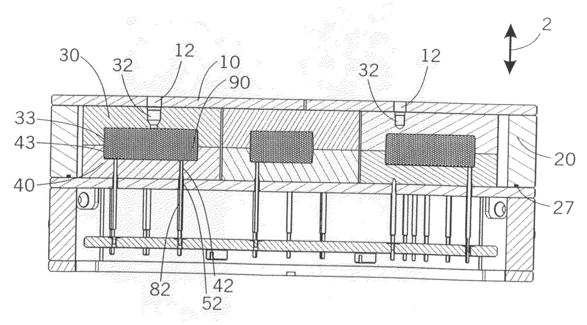
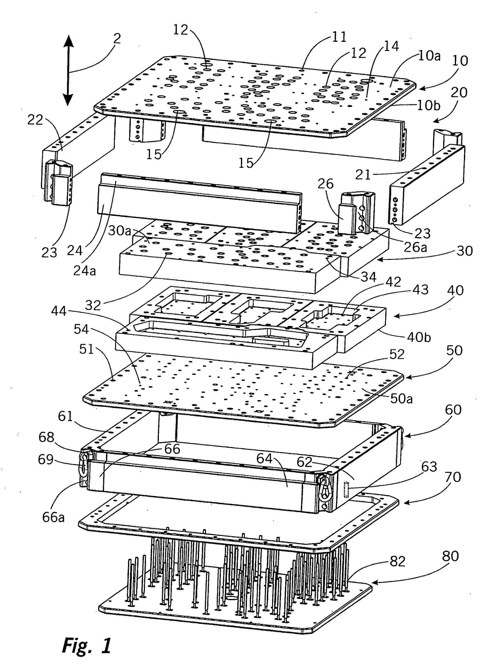
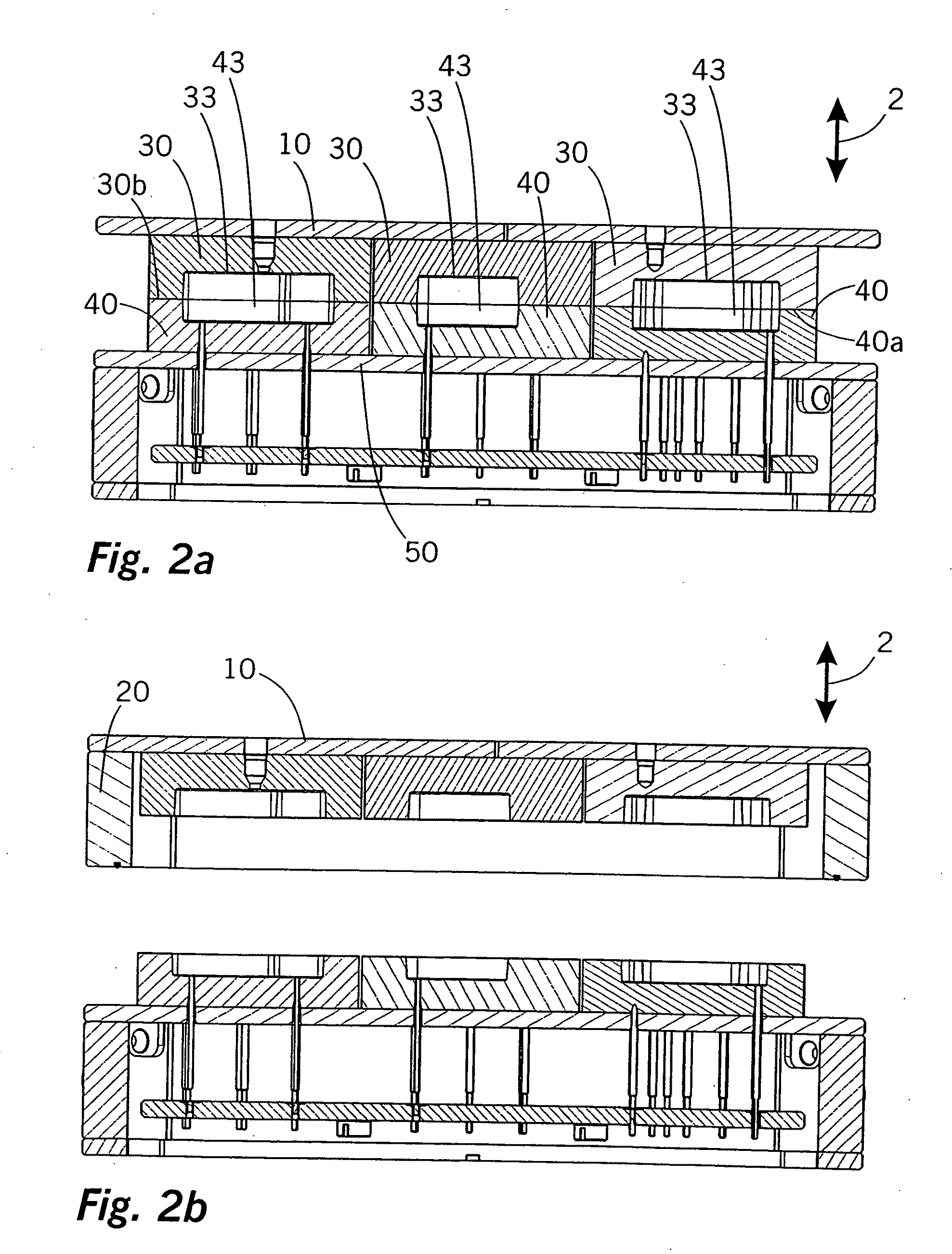
[0044]FIG. 1 is an exploded view of a casting tool of the invention. This casting tool is a core-making tool comprising the following main components that are explained below with reference to FIG. 1 from top to bottom thereof.

[0045]A first supporting plate 10 forms the top closure of the core-making tool. A first frame 20 can be screwed to this first supporting plate with the aid of screws (not shown) so that the first supporting plate 10 and the first frame 20 can be joined together to form a first, top supporting unit 10, 20 for first mold elements 30. In all, four first mold elements 30 are mounted in the bottom-open molding box formed by the first supporting plate 10 and the first frame 20. These first mold elements 30 each comprise bottom-open mold recesses 33 (not shown in FIG. 1), and the four mold recesses 33 of the first mold elements 30 form, together with corresponding top-open mold recesses 43 of four corresponding second mold elements 40, closed cavities representing a...


PUM

PropertyMeasurementUnit
Lengthaaaaaaaaaa
Lengthaaaaaaaaaa
Distanceaaaaaaaaaa

Abstract

The invention relates to a casting tool for the production of castings, particularly for the production of cores (90) for sand castings, comprising a supporting device consisting of a first and a second supporting unit (10, 20, 50, 60) capable of being moved in a joining direction (2) toward each other, and comprising at least two mold elements (30, 40), of which a first mold element (30) is attached to the first supporting unit (10, 20) and a second mold element (40) is secured to the second supporting unit (50, 60), which mold elements (30, 40) each have a mold recess (33, 43), which mold recesses (33, 43) in the mold elements (30, 40) together define the shape of at least one casting core to be produced (90) when the first and second mold elements (30, 40) bear against each other.
According to the present invention, one of the supporting units (10, 20) has a first peripheral frame (20) that surrounds the mold element (30) attached to said supporting unit (10, 20), and the frame (20), as multi-segment frame, is composed of at least two frame segments (22, 24, 26) joined together by positively effective securing means.
The use thereof as a very simply and quickly produced core-casting tool.

Description

TECHNICAL FIELD AND PRIOR ART[0001]The invention relates to a casting tool for the production of castings, in particular cores for sand castings, pressure die castings, and gravity die castings. A generic casting tool comprises a supporting device comprising first and second supporting units which can move toward and away from each other in a joining direction. Furthermore, a generic casting tool of such kind comprises at least two mold elements, of which a first mold element is mounted on the first supporting unit and of which a second mold element is mounted on the second supporting unit. The first and second mold elements each comprise mold recesses oriented toward each other, the mold recesses of the first and second mold elements jointly defining the shape of at least one workpiece to be produced such as a casting core, when the first and second mold elements bear against each other and the mold is thus closed. Furthermore, the invention relates to a core-making machine compris...

Claims


Application Information

Patent Timeline
IPC IPC(8): B22C13/12
CPCB22C7/06B22C7/067B22C7/062
Inventor HERZOG, IVO
Owner HERZOG & HERZOG HLDG & SERVICE
Why Eureka
Try Eureka