
Insulation block for polysilicon ingot furnace and polysilicon ingot furnace including the insulation block

A polycrystalline silicon ingot furnace and heat insulation block technology, which is applied in the directions of polycrystalline material growth, single crystal growth, single crystal growth, etc., can solve the problem of the increase of the chemical time and cooling time, the increase of thermal stress, the rapid increase of dislocation density, etc. problems, to achieve the effect of inhibiting the growth of dislocation density, reducing the radial temperature gradient, and shortening the chemical time.

Active Publication Date: 2017-04-12
HUAZHONG UNIV OF SCI & TECH
View PDF12 Cites 0 Cited by
  • Summary
  • Abstract
  • Description
  • Claims
  • Application Information

AI Technical Summary

Problems solved by technology

The directional solidification process of polysilicon is usually accompanied by the rise of the heat insulation cage or the downward movement of the bottom heat insulation plate. The heat exchange block is used to realize the heat dissipation at the bottom of the crucible. However, in the early stage of nucleation, the heat dissipation is faster in the corner area of ​​the bottom of the crucible, so that the crystal grains near the crucible wall Rapid growth forms a fine-grained region, the grain boundary deviates from the growth direction, and the solidification interface is concave to the melt. The segregation effect makes impurities concentrate in the silicon ingot, further reducing the photoelectric conversion efficiency of the silicon wafer
In addition, when the cooling of the polycrystalline silicon ingot begins, the internal temperature of the silicon ingot is high, and the heat dissipation of the side wall of the crucible is too fast, which increases the radial temperature gradient of the silicon ingot near the wall, resulting in an increase in the thermal stress here, and the dislocation caused by the thermal stress at high temperature The rapid increase in density is not conducive to the growth of high-quality polysilicon ingots
[0005] Chinese patent application 200820031102.X discloses a thermal field structure of polysilicon ingot furnace with graphite cooling block insulation bar, which includes thermal insulation cage body, heater, graphite cooling block and insulation installed around the bottom of graphite cooling block This structure can reduce the content of crystallites in the effective area, so that the content of crystallites in the produced crystal ingot is 0%, but it cannot inhibit the preferential crystallization near the crucible wall, and the dislocation density inside the silicon ingot near the crucible wall is relatively high. large, so it still has the above defects
[0007] However, in this solution, since the groove is arranged on the cooling block, it will firstly affect the heat exchange efficiency of the crucible, so that the materialization time and cooling time will be greatly increased; secondly, since the crucible is covered on the groove, the bottom of the crucible The suppression of the rapid growth of sidewall grains and the rapid growth of dislocation density inside the silicon ingot at the sidewall of the crucible during the cooling process are limited, and the quality of the silicon ingot is not high enough

Method used


Image

  • Insulation block for polysilicon ingot furnace and polysilicon ingot furnace including the insulation block
  • Insulation block for polysilicon ingot furnace and polysilicon ingot furnace including the insulation block
  • Insulation block for polysilicon ingot furnace and polysilicon ingot furnace including the insulation block

Examples


Embodiment Construction

[0024] In order to make the object, technical solution and advantages of the present invention clearer, the present invention will be further described in detail below in conjunction with the accompanying drawings and embodiments. It should be understood that the specific embodiments described here are only used to explain the present invention, not to limit the present invention. In addition, the technical features involved in the various embodiments of the present invention described below can be combined with each other as long as they do not constitute a conflict with each other.

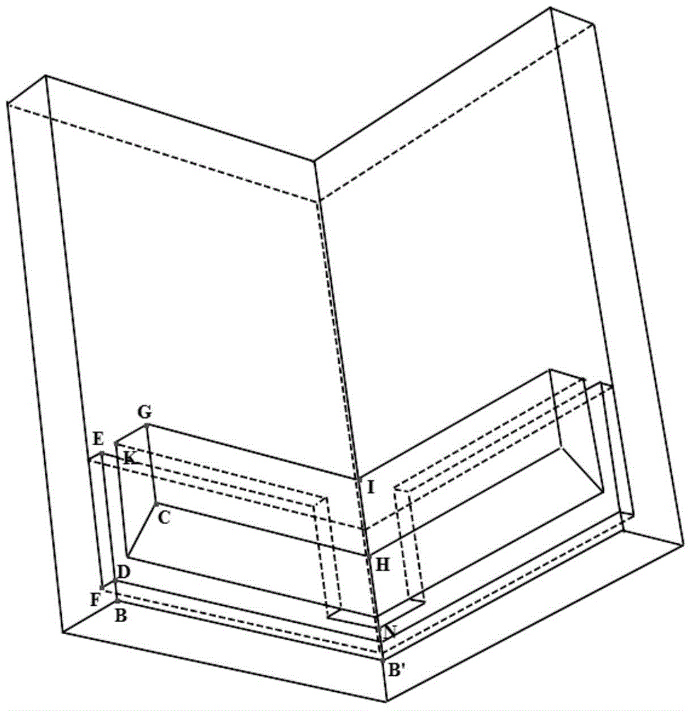
[0025] see Figure 1-3 According to the embodiment of the present invention, the inner and outer walls of the top of the insulating block 2 are square, and the inner hollow forms four rectangular parallelepiped gas channels 5 with the same size and symmetrical distribution. The longest side of the gas channel 5 top is parallel to the inner wall, and its size is The sides of the inner walls are ...


PUM


Abstract

The invention discloses a heat insulation block for a polysilicon ingot casting furnace, which is arranged on the periphery of the bottom of a crucible of the polysilicon ingot casting furnace and used for heat insulation in the process of heating or cooling polysilicon with the crucible. The heat insulation block is a hollow square cylinder structure, wherein the wall of the cylinder is a hollow sandwich structure; the inner wall is used for coating the peripheral wall surface of a heat exchange block on the bottom of the crucible; a clearance is arranged between the inner wall and the peripheral wall surface of the heat exchange block; the outer wall is used for fixedly contacting a vertical heat insulation plate on the periphery of the crucible; the central line of the crucible, the central line of the heat exchange block and the central line of the heat insulation block coincide; and the top of the heat insulation block is lower than the top of the heat exchange block. The invention also discloses an ingot casting furnace provided with the heat insulation block. The heat insulation block can shorten the material melting time in the silicon ingot casting process, lowers the energy consumption, and can effectively inhibit the preferential growth of crystal grains near the crucible wall in the early nucleation period to obtain a slightly-convex and flat freezing interface, thereby enhancing the quality of the silicon ingot.

Description

technical field [0001] The invention relates to the technical field of polysilicon ingot casting furnaces, in particular to a heat insulating block used in a polysilicon ingot casting furnace and a polysilicon ingot casting furnace including the heat insulating block. [0002] technical background [0003] Solar photovoltaic power generation is a form of sustainable energy utilization. It has many advantages such as green and pollution-free, relatively abundant resources, no geographical restrictions, and reliable system operation, making it attract more and more attention. Polycrystalline silicon solar cells have become one of the most important photovoltaic products due to their low cost, high conversion efficiency, and ease of mass production. [0004] Polycrystalline silicon ingots in polycrystalline silicon solar cells are usually prepared by casting. At present, the casting method of polycrystalline silicon ingots is mostly directional solidification. When polysilicon ...

Claims


Application Information

Patent Timeline
Patent Type & Authority Patents(China)
IPC IPC(8): C30B28/06C30B29/06
Inventor 方海生王森蒋志敏郑江张梦杰金泽林
Owner HUAZHONG UNIV OF SCI & TECH
Learn More