Eureka AIR delivers breakthrough ideas for toughest innovation challenges, trusted by R&D personnel around the world.

Variable-frequency simulated hand-wash motor reduction clutch and washing machine

A clutch device and hand rubbing technology, applied in the field of washing machines, can solve the problems of being unsuitable for mass production, complicated installation and connection, and many main parts connecting parts, etc., and achieve the effects of being suitable for popularization, increasing washing capacity, and compact installation structure.

Active Publication Date: 2015-02-25
QINGDAO HAIER WASHING MASCH CO LTD
View PDF10 Cites 10 Cited by
  • Summary
  • Abstract
  • Description
  • Claims
  • Application Information

AI Technical Summary

Problems solved by technology

However, the patented technical solution is simply to install the single-phase asynchronous motor installed next to the deceleration clutch of the washing machine directly and vertically below the clutch; since the efficiency of the motor has not been greatly improved, the washing method is single, the function is simple, and its installation and connection are complicated. , high precision requirements, not suitable for mass production, and the washing machine cannot realize frequency conversion rubbing washing, frequency conversion multi-speed dehydration
Another example is that the patent No. ZL00234747.4 discloses a washing machine deceleration clutch directly driven by a brushless motor. It is complex and can only be used in ordinary washing methods. There are many connecting parts of the main parts, and the requirements for clutch installation accuracy are too high, and it has the disadvantage of high failure rate. Therefore, this patented technical solution is not suitable for mass production

Method used


Image

  • Variable-frequency simulated hand-wash motor reduction clutch and washing machine
  • Variable-frequency simulated hand-wash motor reduction clutch and washing machine
  • Variable-frequency simulated hand-wash motor reduction clutch and washing machine

Examples


Embodiment 1

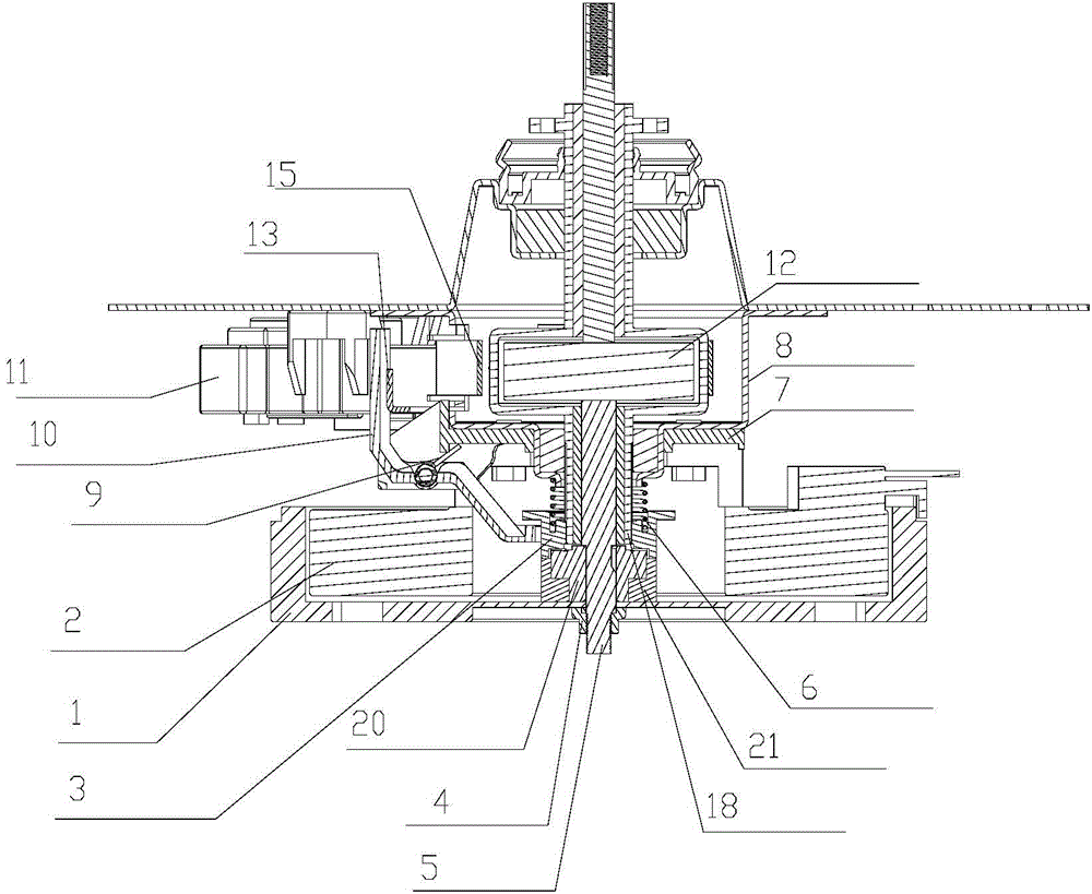
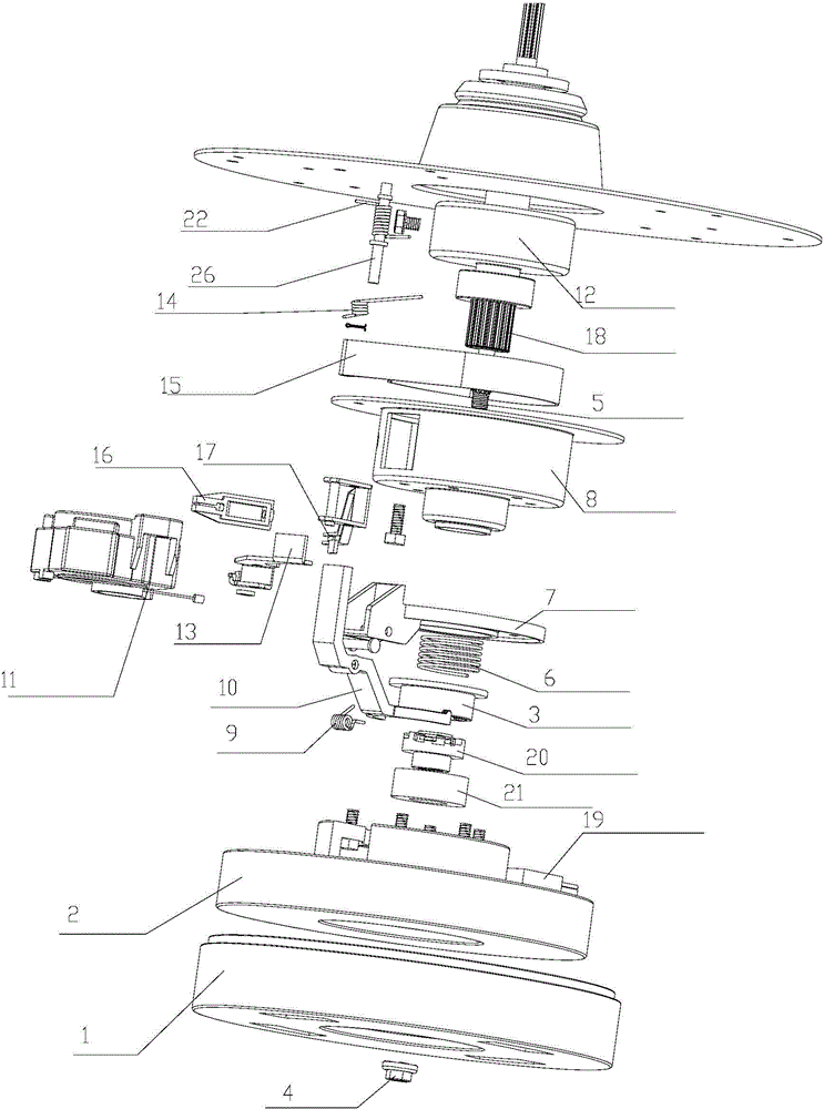
[0034] Such as figure 1 and figure 2 As shown, in this embodiment, a frequency conversion hand rub type motor deceleration clutch device is introduced, including: an input shaft 5, a motor rotor 1 fixedly connected with the input shaft 5, and a dehydration shaft rotating with it is installed on the input shaft 5 Sleeve 20, the dehydration shaft sleeve 20 engages or disengages with the input shaft 5 through the clutch shaft sleeve 3 sliding up and down; the brake wheel 12 is connected with the dehydration shaft 18; under the action of the control device, the traction motor 11 Produce a displacement traction brake belt 5 and change from embracing the brake wheel 12 to loosen the brake wheel 12; the traction motor 11 produces a displacement again to make the clutch sleeve 3 and the input shaft 5 change from disengagement to engagement.

[0035] In this embodiment, the motor is composed of an outer rotor 1 motor composed of a rotor 1 connected to the input shaft 5 and a stator 2...

Embodiment 2

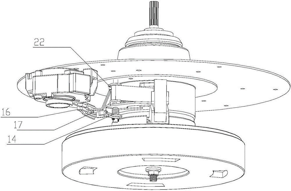
[0044] Such as figure 1 and figure 2 As shown, in this embodiment, the specific connection structure of the control device of the clutch device is as follows: one end of the connecting arm 16 is provided with a mounting groove fixedly connected with the displacement output end of the traction motor 11, and the other end is formed by a square through hole. ; The brake arm 17 is installed in the square through hole. The braking arm 17 is mounted on its lower part rotatably around the mounting pin shaft 26 , and the mounting pin shaft 26 is arranged on the housing 8 . One end of the brake arm 17 is connected to the connecting arm 16, and the other end is fixedly connected to the brake band 15 as the first output end. output. Described depression bar 13 is installed on its top around the mounting pin shaft 26 rotatably. One end of the pressing rod 13 is in contact with or out of the brake arm 17 , and the other end is in contact with the shift fork 10 . The shift fork 10 is ...

Embodiment 3

[0054] This embodiment introduces a control method of a frequency conversion hand rubbing motor deceleration clutch device, which includes: the traction motor drives the connecting arm to generate the first displacement, so that the brake band is separated from the brake wheel on the dehydration shaft, and the dehydration shaft It can rotate freely; it drives the connecting arm to produce a second displacement, so that the clutch sleeve and the dehydration sleeve are engaged, so that the dehydration shaft rotates together with the input shaft.

[0055] The deceleration clutch device of the frequency conversion hand rubbing motor includes three states: the first state, the brake band hugs the brake wheel, and the dehydration bushing is separated from the clutch bushing. At this time, the input shaft can follow the rotor of the motor Rotate, the dehydration shaft is locked and cannot rotate;

[0056] In the second state, the brake band releases the brake wheel, and the dehydrati...


PUM


Abstract

A frequency-variable hand rubbed-type motor speed reduction clutch apparatus, and a washing machine. The clutch apparatus comprises: an input shaft (5) connected to a motor rotor (1); a dehydration shaft (18); and a clutch apparatus housing (8) in which the input shaft (5) and the dehydration shaft (18) are mounted. A braking wheel (12) and a braking belt (15) fitted to the braking wheel (12) are disposed on the dehydration shaft (18). A dehydration shaft sleeve (20) rotating together with the input shaft (5) is mounted on the input shaft (5). A clutch shaft sleeve (3) sliding up and down, and engaging with or separated from the dehydration shaft sleeve (20) is mounted on the dehydration shaft (18). The braking belt (15) and the clutch shaft sleeve (3) are separately connected to a traction motor (11) by means of a control apparatus. The traction motor (11) generates a first displacement, the first displacement is transmitted by the control apparatus and drives the braking belt (15) to move, so that the braking belt (15) changes from grasping the braking wheel (12) to loosening the braking wheel (12), and the dehydration shaft (18) changes from a braked state to a free rotation state. The traction motor (11) generates a second displacement, the second displacement is transmitted by the control apparatus and drives the clutch shaft sleeve (3) to move, so that the clutch shaft sleeve (3) changes from being separated from to engaging with the dehydration shaft sleeve (20), and the dehydration shaft (18) rotates together with the input shaft (5).

Description

technical field [0001] The invention relates to the field of washing machines, in particular to a decelerating clutch device for a frequency-converting hand-rubbing motor and a washing machine. Background technique [0002] Existing technology is installed side by side with washing machine deceleration clutch and single-phase asynchronous motor as the washing machine newly released on the market, by belt pulley and belt transmission. The deceleration clutch of this type of washing machine has low efficiency, high noise, and poor practicability; therefore, relevant technical personnel have proposed a technical scheme in which the motor and the clutch are vertical and coaxially installed. For example, the Chinese utility model patent No. ZL00260194.x discloses a fully automatic washing machine with cup-shaped rotor single-bearing motor and its special clutch device. transmission efficiency. However, the patented technical solution is simply to install the single-phase asynch...

Claims


Application Information

Patent Timeline
Patent Type & Authority Applications(China)
IPC IPC(8): D06F17/08F16D67/02
CPCD06F17/08D06F37/30F16D67/02D06F37/206F16D67/06H02K7/10
Inventor 吕佩师杨林张刚金田云郝晓峰
Owner QINGDAO HAIER WASHING MASCH CO LTD
Why Eureka
Eureka Blog
Learn More