Efficient variable frequency motor speed reduction and clutch device and washing machine

A technology of clutch device and variable frequency motor, which is applied in the field of washing machines, can solve the problems of complex installation and connection, many connecting parts of the main body parts, and the efficiency of the motor is not greatly improved, so as to achieve increased washing capacity, simple structure, and reduced height. Effect

Active Publication Date: 2015-02-25
QINGDAO HAIER WASHING MASCH CO LTD
View PDF15 Cites 4 Cited by
  • Summary
  • Abstract
  • Description
  • Claims
  • Application Information

AI Technical Summary

Problems solved by technology

However, the patented technical solution is simply to install the single-phase asynchronous motor installed next to the deceleration clutch of the washing machine directly and vertically below the clutch; since the efficiency of the motor has not been greatly improved, the washing method is single, the function is simple, and its installation and connection are complicated. , high precision requirements, not suitable for mass production, and the washing machine cannot realize frequency conversion rubbing washing, frequency conversion multi-speed dehydration
Another example is that the patent No. ZL00234747.4 discloses a washing machine deceleration clutch directly driven by a brushless motor. It is complex and can only be used in ordinary washing methods. There are many connecting parts of the main parts, and the requirements for clutch installation accuracy are too high, and it has the disadvantage of high failure rate. Therefore, this patented technical solution is not suitable for mass production

Method used


Image

  • Efficient variable frequency motor speed reduction and clutch device and washing machine
  • Efficient variable frequency motor speed reduction and clutch device and washing machine
  • Efficient variable frequency motor speed reduction and clutch device and washing machine

Examples


specific Embodiment 1

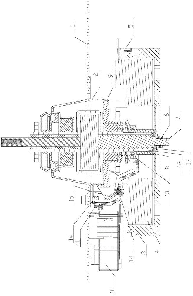
[0024] A high-efficiency variable frequency motor deceleration clutch device, comprising: an outer rotor motor composed of a rotor 3 and a stator 4, and an input shaft 7 fixedly connected to the rotor 3; the input shaft 7 is relatively axially rotatable through an oil-impregnated bearing 17. Inside the input shaft sleeve 16; a clutch shaft sleeve 8 is arranged between the casing and the rotor 3; The input shaft sleeve 16 is connected in a non-rotatable manner; a clutch spring 13 is arranged between the clutch shaft sleeve 8 and the housing; the clutch shaft sleeve 8 is connected with the traction motor 10 through the control mechanism; the clutch shaft sleeve 8 is connected between the control mechanism and the traction motor 10 Under the action of , the clutch sleeve slides up and down to switch between the first position and the second position.

[0025] In this embodiment, when the clutch sleeve 8 is in the first position, the input sleeve 8 engages with the fixed bracket 9...

specific Embodiment 2

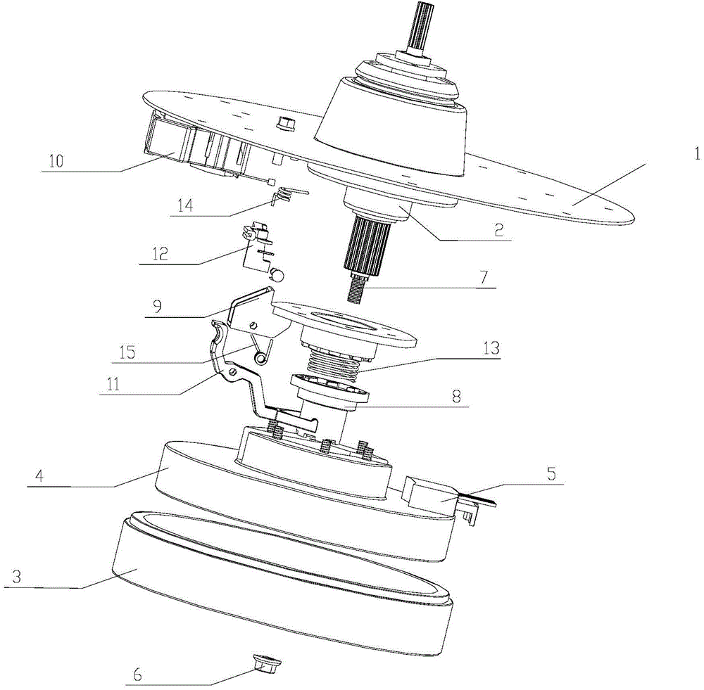
[0032] In this embodiment, the clutch sleeve 8 is connected with the traction motor through a control mechanism. Therefore, the clutch sleeve 8 slides up and down under the action of the traction motor 10, so that the clutch sleeve 8 is switched between the first position and the second position.

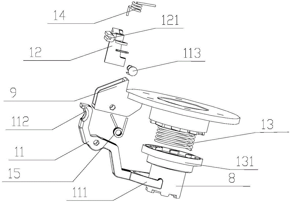
[0033] In this embodiment, the control mechanism includes a connecting arm connected to the traction motor 10 to generate a controlled displacement, a shift fork 11 that is rotatably connected to the housing to limit the position of the clutch bushing 8, and a clutch bushing 8 provides a clutch spring 13 with a sliding force; the shift fork 11 is driven by the connecting arm 12 to contact and limit the clutch sleeve 8 to slide downward.

[0034]In this embodiment, one end of the connecting arm 12 is connected to the traction motor 10 , and the other end is provided with a blocking arm 121 that limits the displacement of the shift fork 11 ; the connecting arm 12 is mounted on the hou...

specific Embodiment 3

[0043] In this embodiment, a washing machine equipped with a high-efficiency variable frequency motor deceleration clutch device includes: an outer tub installed in the body, an inner tub, and a pulsator arranged in the inner tub; the clutch device is fixedly installed on the washing machine, The input shaft is connected with the pulsator of the washing machine through a reduction gear, so that the input shaft drives the pulsator of the washing machine to rotate. The input shaft sleeve is engaged with the dehydration shaft through the transmission mechanism, so that the input shaft sleeve drives the inner tub of the washing machine to rotate.

[0044] When washing, the clutch sleeve is in the first position, the pulsator rotates, and the inner tub does not rotate; when dehydrating, the clutch sleeve is in the second position, the pulsator and the inner tub rotate simultaneously.


PUM


Abstract

The invention relates to the field of washing machines, in particular to an efficient variable frequency motor speed reduction and clutch device and a washing machine. The speed reduction and clutch device comprises a clutch device shell, an external rotor motor and an input shaft (7), wherein the external rotor motor is composed of a rotor (3) and a stator (4), and the input shaft (7) is fixedly connected to the rotor (3) and mounted on the shell. An input shaft sleeve (16) capable of rotating relatively around an axis is arranged outside of the input shaft (7), a clutch shaft sleeve (8) capable of sliding up and down is mounted on the input shaft sleeve (16), and the clutch shaft sleeve (8) is connected to a traction motor (10) through a control mechanism. When the clutch shaft sleeve (8) is located at a first position, the input shaft sleeve (16) is meshed with the shell through the clutch shaft sleeve (8), and when the clutch shaft sleeve (8) is located at a second position, the input shaft sleeve (16) is meshed with the rotor (3) through the clutch shaft sleeve (8). The controllable traction acting force of the traction motor is transmitted to the clutch shaft sleeve through the control mechanism formed by a connecting arm, a shifting fork and a clutch spring, and the clutch shaft sleeve can slide up and down.

Description

technical field [0001] The invention relates to the field of washing machines, in particular to a high-efficiency variable frequency motor deceleration clutch device and a washing machine. Background technique [0002] Existing technology is installed side by side with washing machine deceleration clutch and single-phase asynchronous motor as the washing machine newly released on the market, by belt pulley and belt transmission. The deceleration clutch of this type of washing machine has low efficiency, high noise, and poor practicability; therefore, relevant technical personnel have proposed a technical scheme in which the motor and the clutch are vertical and coaxially installed. For example, the Chinese utility model patent No. ZL00260194.x discloses a fully automatic washing machine with cup-shaped rotor single-bearing motor and its special clutch device. transmission efficiency. However, the patented technical solution is simply to install the single-phase asynchronou...

Claims


Application Information

Patent Timeline
Patent Type & Authority Applications(China)
IPC IPC(8): D06F37/40
CPCD06F37/304D06F37/40
Inventor 杨林张刚金田云杨旭光
Owner QINGDAO HAIER WASHING MASCH CO LTD
Why Eureka
Try Eureka