A leak-proof water inlet valve

A water inlet valve, anti-leakage technology, applied in valve details, valve devices, water supply devices, etc., can solve the problems of adding sliders and baffles, inability to separate, affecting the normal operation of the water inlet valve, etc., to reduce high precision requirements. , Simple structure, stable work effect

Active Publication Date: 2016-08-24
XIAMEN R&T PLUMBING TECH
View PDF6 Cites 0 Cited by
  • Summary
  • Abstract
  • Description
  • Claims
  • Application Information

AI Technical Summary

Problems solved by technology

[0003] In practical applications, dust tends to accumulate on the top surface of the slider, which increases the friction between the slider and the baffle, and even causes the slider and the baffle to be inseparable. Due to the friction between the plates, the small floating bucket cannot lift the slider and separate from the block, thus affecting the normal operation of the water inlet valve

Method used


Image

  • A leak-proof water inlet valve
  • A leak-proof water inlet valve
  • A leak-proof water inlet valve

Examples


Embodiment 1

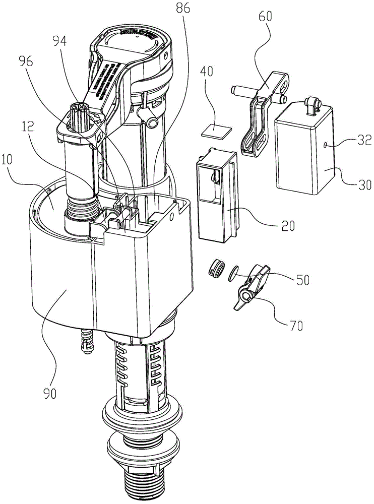
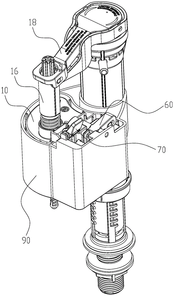
[0035] Please refer to figure 1 with figure 2 , a leak-proof water inlet valve of the present invention, comprising a water inlet valve control mechanism movably mounted on the water inlet valve, a floating bucket adjustment mechanism, a first magnetic piece 40 and a second magnetic piece 50, the first magnetic piece The suction part 40 is connected to the floating bucket adjustment mechanism by transmission, and the second magnetic suction part 50 is connected to the water inlet valve control mechanism by transmission. The first magnetic suction part 40 and the second magnetic suction part 50 are magnetically matched; A magnetic attraction 40 is far away from the second magnetic attraction 50; when the water tank leaks, the floating bucket adjustment mechanism drives the first magnetic attraction 40 close to the second magnetic attraction 50 and magnetically cooperates with the second magnetic attraction 50.

[0036] In this embodiment, the water inlet valve control mechani...

Embodiment 2

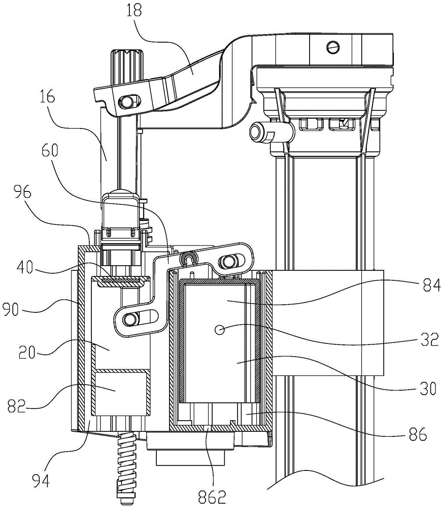
[0046] Please refer to Figure 7 to Figure 10 The difference between the second embodiment and the first embodiment is that: the outer side of the water stop cup 90a is provided with a first storage chamber 86a and a second storage chamber 94a which are arranged side by side and open up and down, and the control float 30 is arranged in the first storage chamber 86a. The leak-proof floating bucket 20 is arranged in the second storage chamber 94a; a counterweight chamber 88 is arranged on the leak-proof floating bucket 20, and a drain hole 882 is provided at the bottom of the counterweight chamber 88; the first seesaw bar 60a is V-shaped A connecting rod 14 is connected to the water-stop floating bucket 10a, and the connecting rod 14 is pivotally connected to the end of the second seesaw rod 70.

[0047] When the water tank is filled with water: at this time, the water tank is empty or the water level is very low, and the leak-proof floating bucket 20 is in a falling state under...


PUM


Abstract

The invention discloses a leakage-proof water inlet valve. The leakage-proof water inlet valve comprises a water inlet valve control mechanism, a keg float adjusting mechanism, a first magnetic attraction piece and a second magnetic attraction piece, wherein the water inlet valve control mechanism can control the water inlet valve to conduct water feeding or conduct water stop, and the keg float adjusting mechanism is movably installed on the water inlet valve in a connected mode. The first magnetic attraction piece is connected with the keg float adjusting mechanism in a transmission mode, and the second magnetic attraction piece is connected with the water inlet valve control mechanism in a transmission mode. The first magnetic attraction piece is matched with the second magnetic attraction piece in an magnetic attraction mode. When a water tank is normal, the keg float adjusting mechanism drives the first magnetic attraction piece to be far away from the second magnetic attraction piece. When the water tank leaks water, the keg float adjusting mechanism drives the first magnetic attraction piece to be close to the second magnetic attraction piece and matched with the second magnetic attraction piece in the magnetic attraction mode. By the adoption of the technical scheme, the keg float adjusting mechanism controls the water inlet valve control mechanism to move in the mode that the first magnetic attraction piece attracts the second magnetic attraction piece, and the structure is simple and compact; in addition, the first magnetic piece and the second magnetic piece can be set to be in gap magnetic matching, in this way, the requirement for the machining precision of the water inlet valve is lowered, cost is reduced, and the performance is reliable.

Description

technical field [0001] The invention relates to an anti-leakage water inlet valve, in particular to a magnetic control type anti-leakage water inlet valve. Background technique [0002] The Chinese invention patent with the notification number CN202689139U discloses a leak-proof structure of the water inlet valve, which includes a baffle connected to the large floating bucket, a small floating bucket connected to the side of the water stop plate by transmission, and a small floating bucket pivotally connected to the small floating bucket. The upper slider, the two sides of the small floating bucket are respectively provided with a counterweight and a counterweight cavity, and the bottom of the counterweight cavity is provided with a drain hole, and the blocking plate is in contact with the slider. During normal drainage, the weight of the water stored in the counterweight chamber is greater than the weight of the counterweight, and the small floating bucket swings toward one...

Claims


Application Information

Patent Timeline
Patent Type & Authority Patents(China)
IPC IPC(8): E03D1/32F16K31/06F16K31/18
CPCE03D1/32F16K31/06F16K31/18
Inventor 张凤荣张祖连钟志军
Owner XIAMEN R&T PLUMBING TECH
Why Eureka
Try Eureka